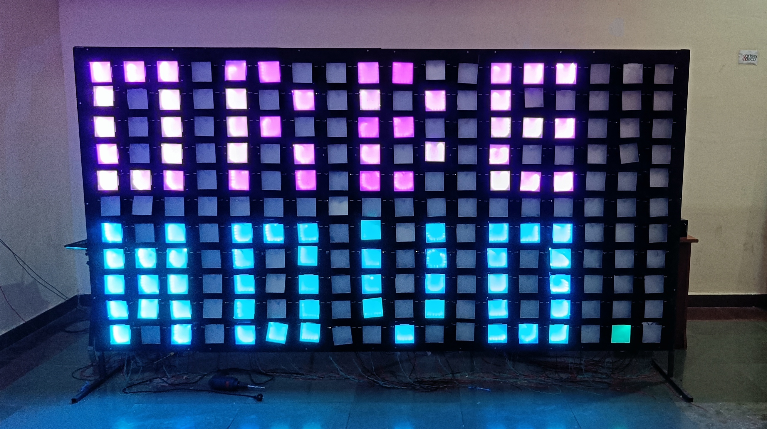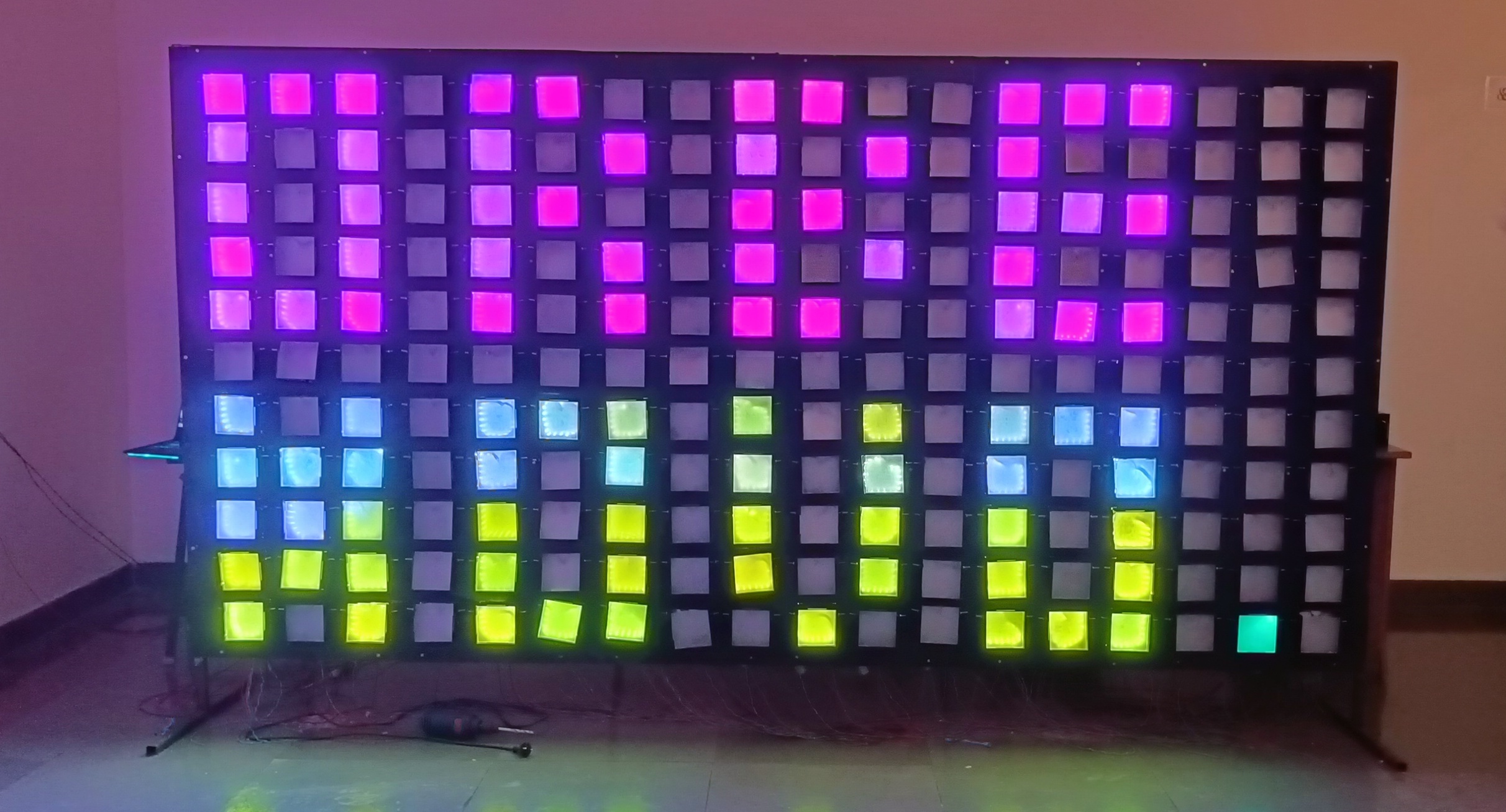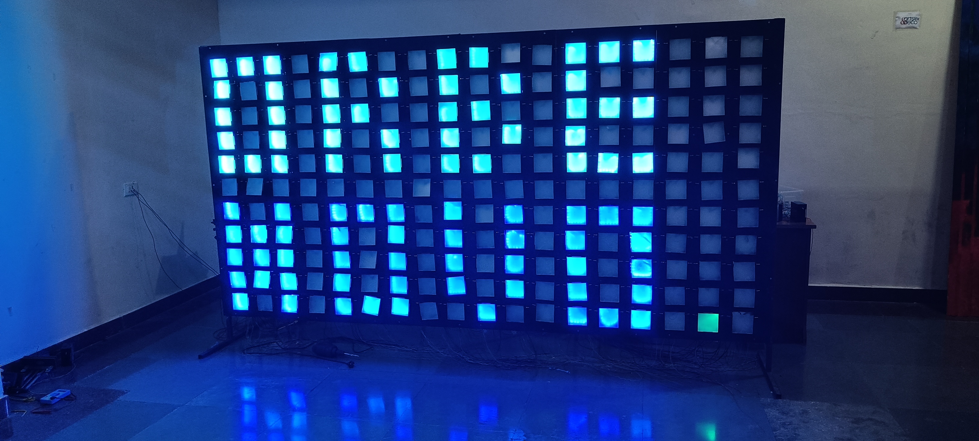
CubeD is an interactive touch-based display that lets users engage and play games.
Mechanical Design
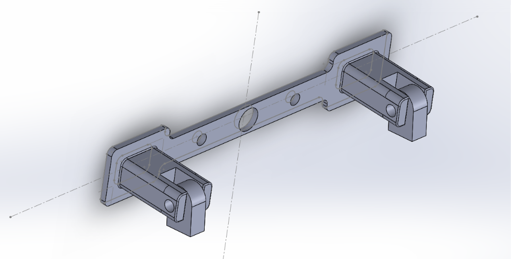
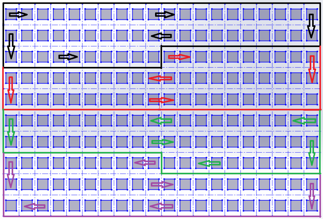
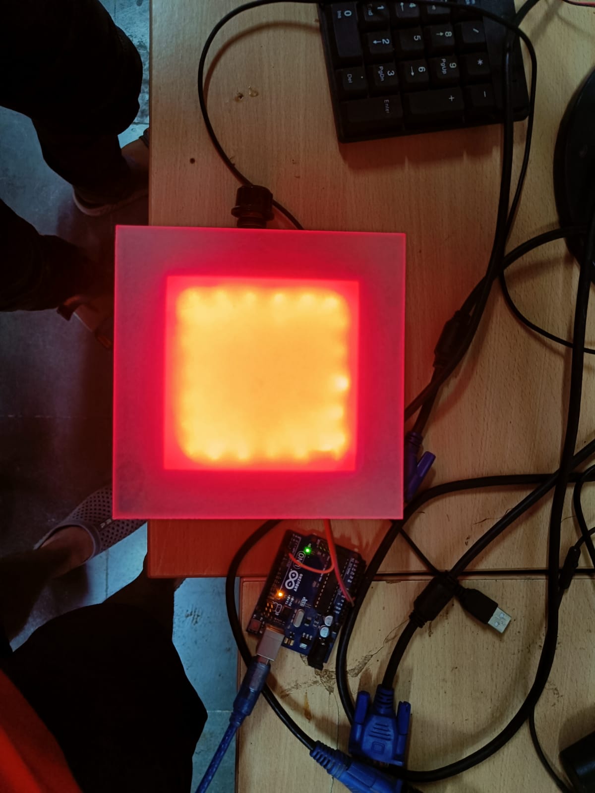
CubeD consists of 200 squares hinged onto a 4 segment steel back panel. Its current dimensions are 3 meters x 2 meters. Each steel back panel measures 1meter x 1.5 meters and houses 50 squares. Each square has 12 - Neopixels arranged around the inner perimeter of the square, a diffuser ensures that that the light is uniformly projected to the user.
The back panels are screwed onto a two-piece wooden frame with triangular support structures. Each square has a microswitch behind it on the panel, which is used as an input device to detect touch from the user.
Electronics
The CubeD has been designed such that it can be assembled and dismantled without any wastage of resources, and hence the electronics and electrical wiring of the entire project is divided into modules that are easy to work on. The Power Supply for CubeD consists of the main power source and two junctions that are branched from the main source.
Neopixels
The WS2812 Integrated Light Source — or NeoPixel in Adafruit parlance — is the latest advance in the quest for a simple, scalable, and affordable full-colour LED. Red, green, and blue LEDs are integrated alongside a driver chip into a tiny surface-mount package controlled through a single wire. Neoxpixels use a Single-Wire Protocol to transfer data.
Writing out WS2812 data requires some pretty tight timing. Tight enough that FastLED disables interrupts while it is writing out led data. This means that while the led data is being written out, any interrupts that happen will be delayed until all the led data is written out.
NeoPixels receive data from a fixed-frequency 800 kHz datastream. One bit, therefore, requires 1/800,000 sec — 1.25 microseconds. One pixel requires 24 bits (8 bits each for red, green blue) — 30 microseconds. After the last pixel’s worth of data is issued, the stream must stop for at least 50 microseconds for the new colours to “latch.”
For a strip of 2400 Pixels, that’s 2400*30 + 50 which is 72,050 microseconds, therefore 13.8 updates per second.
Since the latching is done internally inside the Neopixel strip, the interrupts are only disabled for data transfer.
For a strip of 2400 Pixels, that’s 2400*30 which is 72,000 microseconds. During this time interrupts are disabled on most boards.
Shift Registers
This sequential device loads the data present on its inputs and then move or “shifts” it to its output once every clock cycle, hence the name Shift Register.
A shift register consists of several single bit “D-Type Data Latches”, one for each data bit, either a logic “0” or a “1”, connected together in a serial type daisy-chain arrangement so that the output from one data latch becomes the input of the next latch and so on.
PISO Shift Registers
The parallel data is loaded into the register simultaneously and is shifted out of the register serially one bit at a time under clock control.
The 8 inputs are translated into a series of HIGH and LOW pulses on the serial-out pin of the shift register. This pin should be connected to an input pin on your Arduino Board, referred to as the data pin. The transfer of information on the data pin is called “Synchronous Serial Output” because the shift register waits to deliver a linear sequence of data to the Arduino until the Arduino asks for it. Synchronous Serial communication, either input or output, is heavily reliant on what is referred to as a clock pin. The clock pin is the metronome of the conversation between the shift register and the Arduino, it is what keeps the two systems synchronous. Every time the Arduino changes the clock pin from LOW to HIGH the shift register changes the state of the Serial Output pin, indicating the value of the next switch.
The third pin attached to the Arduino is a “Parallel to Serial Control” pin. It is referred to as a latch pin. When the latch pin is HIGH the shift register is listening to its 8 parallel inputs. When the latch pin is LOW, it listens to the clock pin and passes information serially. That means every time the latch pin transitions from HIGH to LOW the shift register will start passing its most current switch information.
In the current design, we have 4 sets of 7 PISO Registers daisy-chained with a UNO as a sub-unit to process the states of 50 microswitches.
Micro Switches
A Microswitch has three terminals NC, NO, and C (or COM). C is the signal to be switched. NC is normally closed and NO is normally open.
A 5V signal is given to the Common terminal and the output signal from NO is monitored using a digitalRead. Each microswitch is placed behind a square box on the back panel, in such a way that the switch would be triggered when the box is touched. Each NO terminal is connected to the Parallel Input Pin of a PISO Shift Register with the help of a terminal box to maintain the modular structure.
Power Supply
Switching Mode Power Supply units are used as the main power source for CubeD. Multiple SMPS units are used along with Junctions at appropriate places to distribute loads to keep the circuit stable. A key feature in the design is the fact that all the connections made to individual modules are in parallel which ensures the working of other modules in case a single module is down for maintenance.
Each Neopixel grid is powered using one SMPS from both ends, this is to avoid reverse feed from one SMPS to another due to minute changes in the output voltage. All the grounds are interconnected.
NeoPixels don’t care what end they receive power from. Though data moves in only one direction, electricity can go either way. You can connect power at the head, the tail, in the middle, or ideally distribute it to several points. Think of power distribution as branches of a tree rather than one continuous line.
Power Requirements
Each individual NeoPixel draws up to 60 milliamps at maximum brightness white (red + green + blue). In actual use though, it’s rare for all pixels to be turned on that way. When mixing colours and displaying animations, the current draw will be much less.
For a strip of 2400 Pixels at 5V, the current consumption is 144 Amps. Which is around 720 Watts. Therefore, each SMPS should be capable of giving out around 40 Amps and a rated power output of more than 200W.
Terminal Box
Each of the 4 PISO Registers PCB contains around 56 PCB Terminals Soldered onto the PCB for easy connections between the microswitches and the registers.
Junction Box
Junction Boxes are used to distribute power without directly tapping into the main power source and this also helps us keep all the connections modular.
It is also used for interconnecting grounds across the circuits.
Complete Frame