
Introduction
The following notes were created for Techtainment, an event that I conducted to teach the basics of electronics and programming to people who hadn’t previously explored the field of robotics.
Arduino Uno Tech Specs
- Operating voltage = 5V
- Recommended input voltage = 7V-12V
- Input voltage (limit) = 6-20V
- DC current per I/O pin = 40mA
- DC current per 3.3V pin = 50mA
- Flash memory = 32 kB of which 0.5 kB is used by the bootloader
- SRAM = 2 kB
- EEPROM = 1 kB
- Clock speed = 16 MHz
- The ATmega328P chip has 28 pins.
You can check out the datasheet of the ATmega328P chip if interested.
What is the deal with Arduino Uno’s digital pin 13 LED?
Digital pin 13 is harder to use as a digital input than the other digital pins because it has an LED and a resistor attached to it that’s soldered to the board on most boards. If you enable its internal 20k resistor, it will hang at around 1.7V instead of the expected 5V because the onboard LED and series resistor pull the voltage level down, meaning it always returns a LOW. If you must use digital pin 13 as a digital input, set its pinMode() to INPUT and use an external pull-down resistor.
TX/RX
On the Arduino board, pin 0 (RX) and 1 (TX) are used for communicating with the computer. Connecting anything to these pins can interfere with the communication, and can cause failed uploads to the boards.
Purpose of TX and RX LEDs:
The TX and RX LEDs blink whenever there is a communication between the onboard microcontroller and the computer through the USB to Serial Converter chip present near the USB port.
The lighting up of LEDs indicates the direction of flow of data. When a bit of data goes from the Arduino board to the computer, the TX LED glows. When a bit of data goes from the computer to the Arduino, the RX LED glows.
When the computer uploads a code to the Arduino, it sends data to the board to set its fuse bits, determines the inputs and outputs to be used and other necessary instructions to make the code work. The Arduino board replies each time data is sent during the upload to tell the comp that it is receiving the instructions. So when the computer uploads code to the board, the TX and RX LEDs flash rapidly, showing the data exchange process. It is so fast that these LEDs seem to be turned on steadily.
AREF pin
Used as an analog reference pin for analog inputs.
Watch the following video to get a good understanding of why we use the AREF pin: https://youtu.be/qUySekwhXws
Documentation: analogReference()
Crystal Oscillator
What is an oscillator?
In general form, an oscillator is something that creates oscillation, which means that something is moving or swinging back & forth. Now in the context of electrical & electronic engineering oscillations that we talk about is the swinging back & forth of the voltages. An oscillator not only can generate sine waves but it can also generate squarewaves, triangle waves, etc.
What are oscillators used for?
Oscillators are always used in electrical designs but commonly used for generating radio waves,tone generators,generating counters to keep track of time, and generating clock signals to maintain the speed of the digital processors including computers that we are regularly using.
What is the use of a crystal oscillator in Arduino?
Arduino crystals are used because it helps when Arduino is dealing with time issues, for example if we build a project that turns a switch A OFF after 15 minutes ON and turn ON switch B, C & D one after another with a 20 minutes step. We can use Arduino software to program Arduino to do that, but how does Arduino calculate the time?
The answer is by using a crystal oscillator. The number on the top of the Arduino crystal is 16.000H9H this gives us information about the frequency which is 16,000,000 Hertz or 16 Mhz. This small component can make 16 millions cycles per second.
Why does Arduino have a 16 Mhz crystal instead of 32 Mhz or more?
The datasheet of the ATmega328P chip says that the maximum frequency should not exceed 20MHz. Hence a clock of 16 Mhz is used.
What is the accuracy of the crystal?
Arduino crystal has 100ppm accuracy, and these crystals have an error margin of 100 cycles -or+ in each 1 million cycles. This means that the maximum -or+ error in time calculated by Arduino is 30 sec.
Blocking Code
When a program “halts” to execute some code, that code that holds up the program is called blocking code. The delay() function is an example of blocking code. This function decreases the tightness of a loop.
Blocking code is a generic term given to code that is going to take some time to execute and is going to stop other parts of our program from running while it executes.
If you have two repetitive events and those events overlap, then you may find that using the delay function is not the best solution for programming it. We can use an alternative function called millis() instead.
The millis() function will be discussed in detail in the upcoming sessions.
Does the delay() function pause all activities?
Certain things do go on while the delay() function is controlling the ATmega chip, because the delay function does not disable interrupts. Serial communication that appears at the RX pin is recorded, PWM (analogWrite) values and pin states are maintained, and interrupts will work as they should.
We will discuss interrupts in detail in the upcoming sessions.
LDR
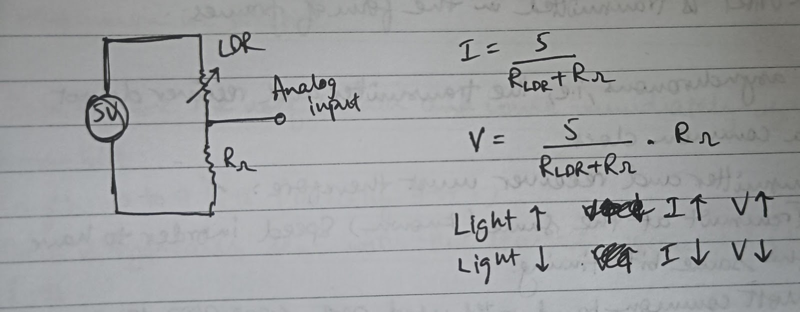
Light Dependent Resistor (LDR) is a device whose resistivity varies with the incident EM radiation. Hence they are light-sensitive devices. Also called photoconductors or photoconductive cells. They do not have a polarity.
When light is incident on the LDR, electrons from the valence band jump to the conduction band, resulting in a decrease in resistance.
We cannot connect an LDR directly to an Arduino pin. This is because on doing so, the current through the LDR changes due to change in its resistance. But the Arduino cannot measure current and it measures only changes in voltage. Therefore in order to use an LDR, we need to connect it in series with another resistor and measure the voltage across that resistor.
Ways to Power Up Your Arduino Uno
Refer to the following link: Power Scheme Methods
PWM from non-PWM pins
Go through the following simulation: TinkerCAD
Code explanation:
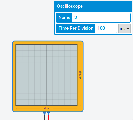
The oscilloscope has a time per division equal to 100ms. The user gives the required duty cycle as input.
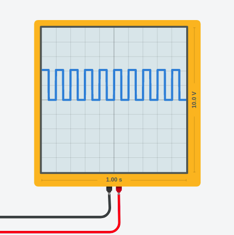
Let’s say the duty cycle required is 50%. This means that the signal should stay HIGH for 50% of the time and stay LOW for the remaining 50% of the time. So in one time division, the signal will stay HIGH for 50ms (50% of 100ms = 50ms) and LOW for the remaining 50ms. This can be achieved by keeping a delay equal to the duty cycle, i.e., 50ms in this case.
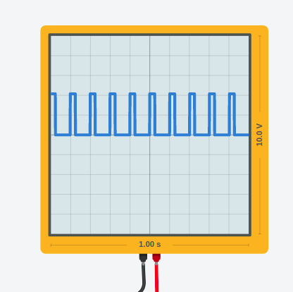
Now let’s say the duty cycle required is 25%. This means that the signal should stay HIGH for 20% of the time and stay LOW for the remaining 75% of the time. So in one time division, the signal will stay HIGH for 25ms (25% of 100ms = 25ms) and LOW for the remaining 75ms (100ms - 25ms). This can be achieved by keeping a delay equal to the duty cycle, i.e., 25ms in this case, for the HIGH signal, and a delay equal to 75ms (100 - duty cycle) for the LOW signal.
So in general, if a particular duty cycle is required, you can give a delay equal to the duty cycle for the HIGH signal, and a delay equal to 100 - duty cycle for the LOW signal.
We are using 100 here because the time per division of the oscilloscope is 100ms. This number can be changed depending on the time per division of the oscilloscope.
You can also notice how the brightness of the LED changes with change in duty cycle.
Servo Motor
Closed loop system based on position feedback to control the motion and position of the shaft. The feedback signal is generated by comparing the output signal and reference input signal.
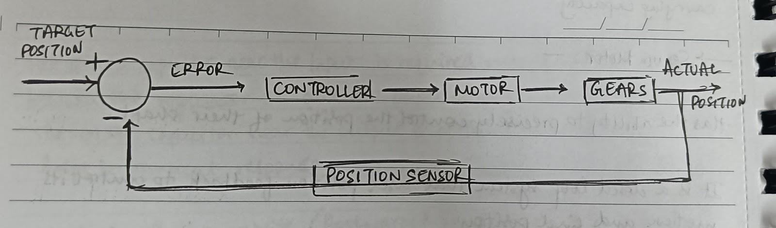
The actual position of the shaft is captured by the potentiometer and is fed back to the error detector where it is compared to the target position. The controller tries to minimize this error and corrects the actual position of the motor to match with the target position.
Components:
- DC Motor - high speed, low torque
- Gearbox - increase torque, reduces rpm
- Potentiometer - attached to the servo shaft. As the motor rotates, the potentiometer rotates as well. This produces a variable voltage related to the absolute angle of the shaft.
- Control circuit - potentiometer voltage is compared to the target voltage signal. If needed, it activates an internal H-bridge which enables the motor to rotate in either direction, until the two signals reach a difference of 0.
When the shaft of the motor is at the desired position, power supplied to the motor is stopped. If not, the motor is turned in the appropriate direction.
The motor’s speed is proportional to the difference between its actual position and desired position. So if the motor is near the target position, it will turn slowly, otherwise it will turn fast. This is called proportional control.
How are Servos controlled?
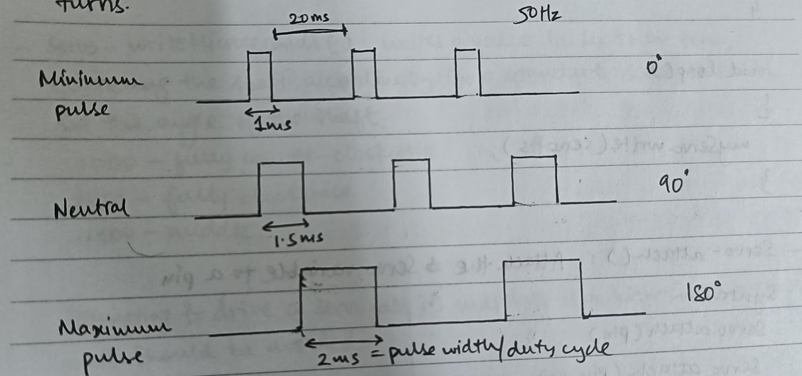
Servos are controlled by sending PWM signals. The PWM sent to the motor determines the position of the shaft, and based on the duration of the pulse sent, the shaft will turn to the desired position.
The servo expects to see a pulse every 20ms (frequency=50Hz) and the length of the pulse will determine how far the motor turns, as shown below.
When servos are controlled to move, they will move to the position and hold that position. If an external force pushes against the servo while it is holding its position, it will resist from moving out of its position.
Torque Rating
https://automaticaddison.com/how-to-determine-what-torque-you-need-for-your-servo-motors/
HC-SR04
Sensor features:
- Operating voltage = 5V
- Theoretical measuring distance: 2cm to 450cm
- Practical measuring distance: 2cm to 80cm
- Accuracy: 3mm
- Measuring angle covered: <15 degrees
- Pulse frequency: 40 kHz
Working:
To start measurement, trig pin of the sensor must be given 5V (HIGH) for 10 microseconds. This will initiate the sensor, transmit out 8 cycles of ultrasonic pulse at 40 kHz and wait for the reflected pulse.
When the pulse is sent, the echo pin is set from LOW to HIGH automatically. On receiving the reflected signal, the echo pin will go back to LOW and produce a pulse. The length/width of the pulse is proportional to the time it took for the transmitted signal to be detected. The width of the pulse varies between 150us-25ms.
If the pulses are not reflected back, the echo signal will timeout after 38ms and return LOW, indicating no presence of an obstacle within the range of the sensor.
The trigger of 10us is to allow the firmware in the microcontroller to recognize the input.
Why transmit 8 cycles?
PIR
Working:
The PIR sensor has 2 slots in it, each made up of a special material sensitive to IR. When the sensor is idle, both slots detect the same amount of IR. When a warm body passes by, it first intercepts one half of the sensor, which causes a positive differential change between the two halves. When the warm body leaves the sensing area, the reverse happens,i.e., it generates a negative differential change. These change pulses are what is detected.
The BISS0001 decoder chip is used in the PIR sensor. It takes the signal from the sensor and does some minor processing on it to emit a digital output pulse from the analog sensor.
UART
The protocol used by Arduino to communicate with the computer is called UART. UART stands for Universal Asynchronous Receiver Transmitter. It defines a protocol for exchanging serial data between two devices, in this case, between the Arduino and computer.
It uses only 2 wires between the transmitter and receiver, TX and RX. The communication can be done is different modes-
- Simplex - data is sent in one direction only
- Half duplex - data is sent in both directions but only one at a time
- Full duplex - data is sent in both directions simultaneously
UART is Asynchronous, which means that the transmitter and receiver do not share a common clock. The transmitter and receiver must therefore
- Transmit at the same known speed inorder to have the same bit timing. Most common baud rates used are 4800, 9600, etc.
- Use the same frame structure
Frame structure:
In the idle state, when no data is being transmitted, the line is held HIGH. This allows for easy detection of a damaged line/transmitter.
The start bit indicates data is coming. It is a transition from the ideal HIGH state to LOW state. User data bits come immediately after the start bit.
After the data bits are finished, the stop bits indicate the end of user data.
The stop bit is either a transition back to the HIGH or idle state or will remain at the HIGH state for an additional bit time. A second optional stop bit can be configured, usually to give the receiver time to get ready for the next frame, but this is uncommon in practice.
Length of data bits: 5-9 bits (usually 7 or 8)
Data is typically sent with the least significant bit (LSB) first.
An optional parity bit can be used for error detection. It is inserted between the end of the data bits and the stop bit.
Even parity: bit is set such that the total no. of 1’s is even
Odd parity: bit is set such that the total no. of 1’s is odd
It can be used to detect only a single flipped bit. If more than one bit is flipped, there is no reliable way to detect these using a single parity bit.