
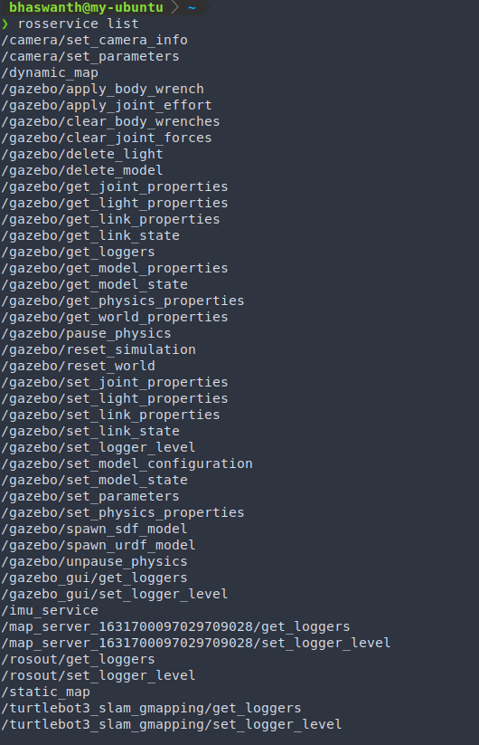
ROS Navigation
1.1 Introduction
The ROS Navigation stack takes in information from odometry, sensor streams, and a goal pose and outputs safe velocity commands that are sent to a mobile base.
The entire process of robot navigation can be divided into 3 major parts:
- Mapping
- Localization
- Path Planning
1.2 Mapping
In order to perform autonomous navigation, the robot must have a map of the environment. The robot will use this map for many things such as planning trajectories, avoiding obstacles, etc.
Rviz is a very important tool that will be used extensively in the mapping process. For Mapping, you will basically need to use 2 displays of Rviz:
- LaserScan Display
- Map Display
1.2.1 SLAM
Simultaneous Localization and Mapping refers to building a map of an unknown environment while simultaneously keeping track of the robot’s location on the map that is being built.
This scenario in Robotics is solved using the gmapping package on ROS.
1.2.2 gmapping package
The gmapping package implements a special SLAM algorithm called gmapping. We don’t need to know how to code the alogrithm ourselves but just need to learn how to configure the package for our robot to suit our needs.
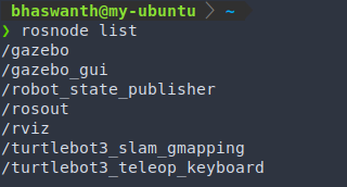
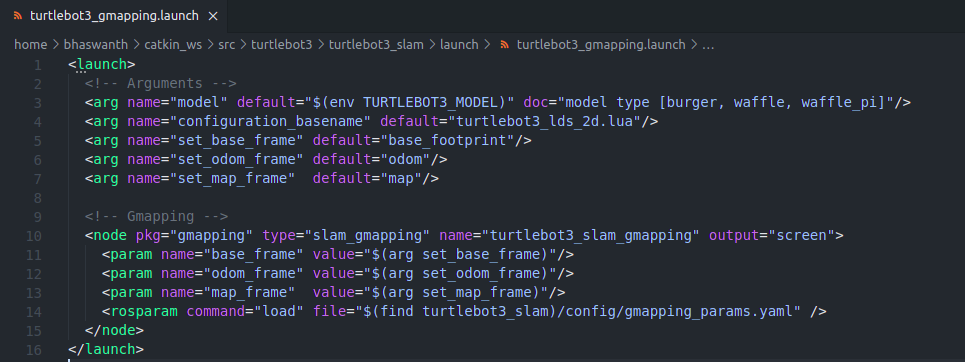
The gmapping package contains a ROS node called slam_gmapping that allows us to create a 2D map using the laser and odom data provided by the robot while navigating the given environment. This node basically reads data from the laser and the transforms of the robot, and turns it into an Occupancy Grid Map (OGM).
Launch gazebo -
roslaunch turtlebot3_gazebo turtlebot3_house.launchLaunch the gmapping package with the robot (turtlebot3 in our case) by using a previously created launch file turtlebot3_gmapping.launch.
To do so, run the command:
roslaunch turtlebot3_slam turtlebot3_gmapping.launchThis launch file starts the turtlebot3_slam_gmapping node from the gmapping package.
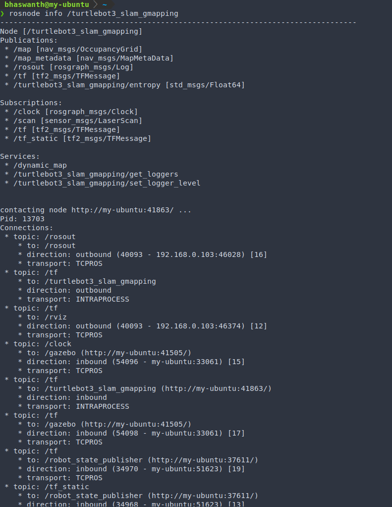
The turtlebot3_slam_gmapping node subscribes to the Laser topic (/scan) and Transform topic(/tf) to get laser and odom data from the robot, which it needs to build the map.
The generated map is published during the whole process into the /map topic, which reflects on Rviz.
In order to visualize this map on Rviz, enter to following command:
roslaunch turtlebot3_gazebo turtlebot3_gazebo_rviz.launchEnter the following command to move the turtlebot3 and to produce a map of the complete environment.
roslaunch turtlebot3_teleop turtlebot3_teleop_key.launch
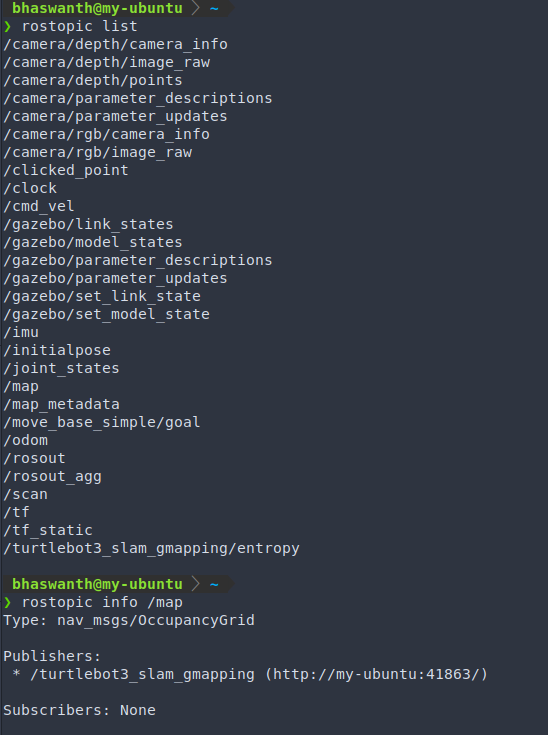
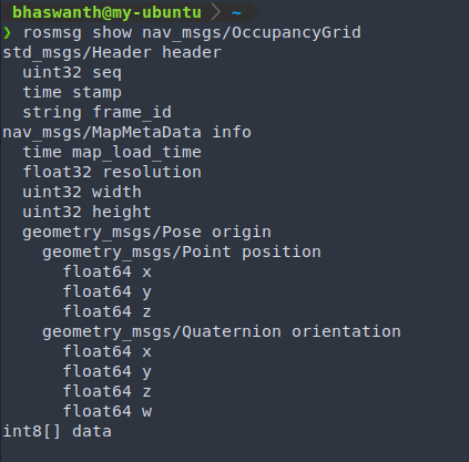
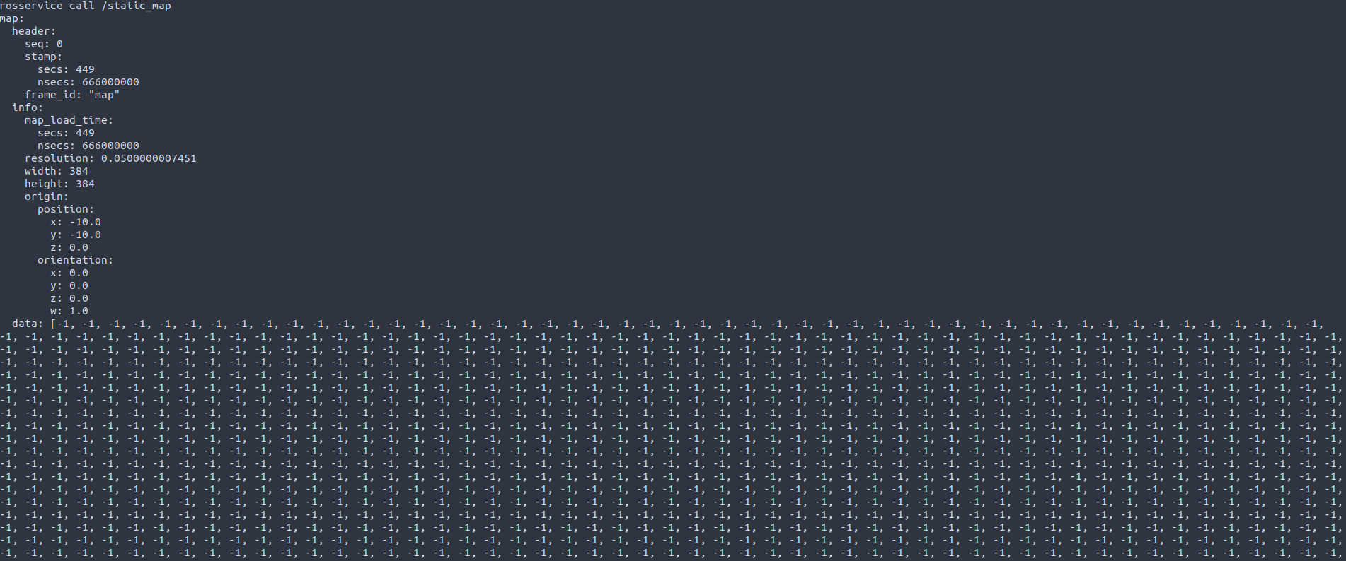
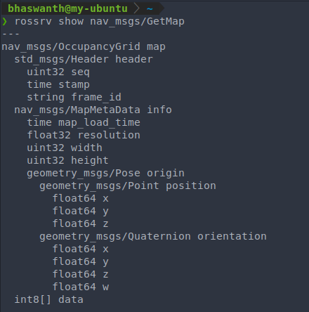
The /map topic uses the message type nav_msgs/OccupancyGrid since it is an OGM. The occupancy is represented as an integer in the range {0,100}.
- 0 implies completely free
- 100 implies completely occupied
- -1 implies completely unknown.
Rviz:
On entering roslaunch turtlebot3_gazebo turtlebot3_gazebo_rviz.launch, you will see something like this on the Rviz window:
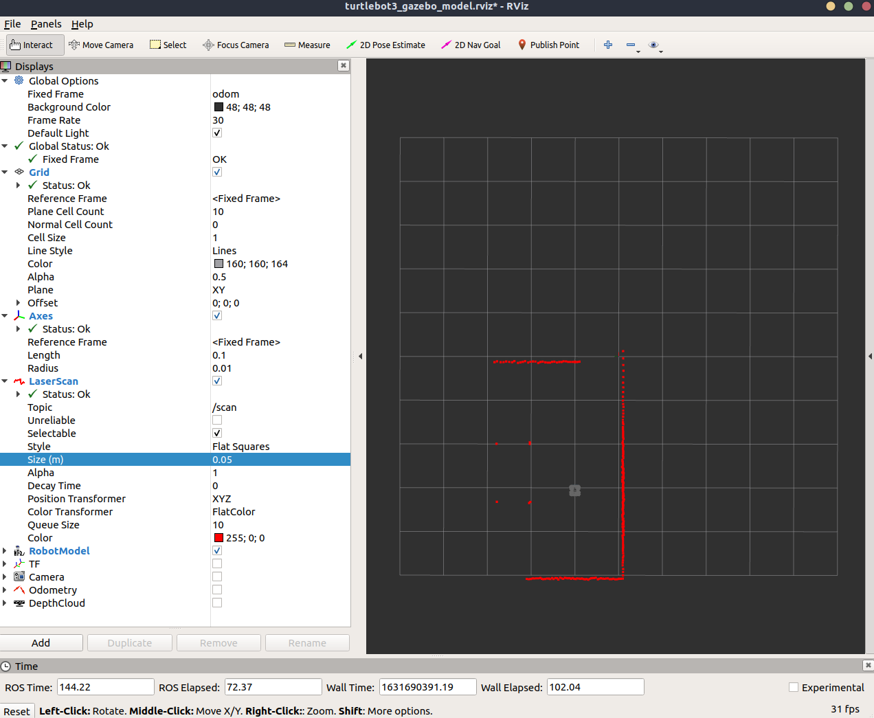
This however, does not have the map display and hence we cannot see the map of the environment produced by the robot. To get the map display, click on “Add” and select “Map”.
Now in the Map display, select the topic name /map to visualize the map being made in real-time by your robot.
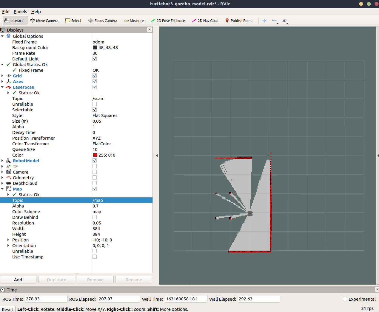
You can now navigate your robot the obtain a map of the complete environment.
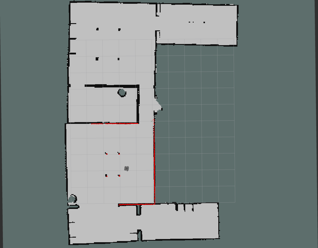
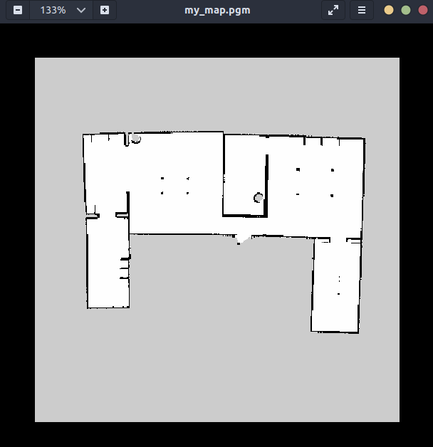
The finished map should look something like this.
1.2.3 map_server
map_server is a package belonging to the ROS Navigation Stack.
Saving a map
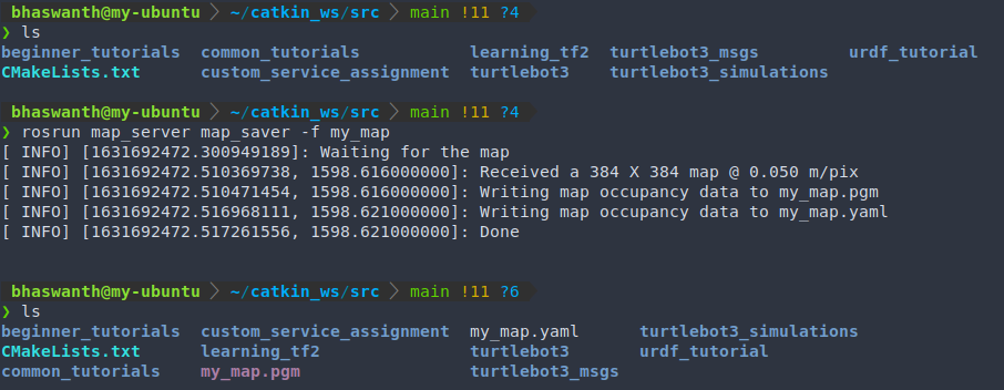
It provides a map_saver node which allows us to access the map data from a ROS Service and save it into a file.
When you request the map_saver to save the current map, the map data is saved into two files:
- YAML file - contains the image name and the metadata of the map
- Image_name.pgm - this contains the image itself, which has the encoded data of the OGM. pgm stands for Portable Gray Map
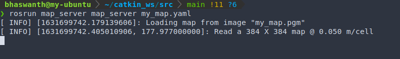
To save the built map, enter the following command: rosrun map_server map_saver -f <map_name>
To open the map image, enter xdg-open <map_name>.pgm
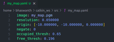
Contents of YAML file:
- image: Name of the file containing the image of the generated map
- resolution: Resolution of the map (in meters/pixel)
- origin: Coordinates of the lower-left pixel in the map. The first two values indicate position and the third value indicates rotation.
- negate: Inverts the colors of the map. 0 by default
- occupied_thresh: Pixels which have a value greater than this value will be considered as completely occupied
- free_thresh: Pixels which have a value smaller than this value will be considered as completely free
Providing a map
The map_server package also provides the map_server node that reads a map file and provides it to any other node that requests it via a ROS Service. This request is done, for example, by the move_base node to get data from a map and use it for Path Planning, or by the localization node in order to find the position of the robot in the map.
The service to call to get the map is /static_map (nav_msgs/GetMap).
Apart from requesting the map through the GetMap service, there are two topics that you can connect to in order to obtain ROS Messages about the map.
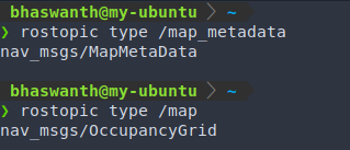
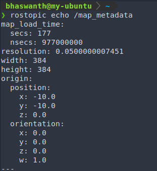
- /map_metadata (nav_msgs/MapMetaData): Provides map metadata
- /map (nav_msgs/OccupancyGrid): Provides the map occupancy data
Enter the following command to launch the map_server node in order to provide the map information: rosrun map_server map_server <map_name>.yaml
The map that is created is a static map which means that the details of the map will not change or update with time. If the environment changes in the future, then these changes will not reflect in the map.
The map that is created is a 2D map, which means that the obstacles that appear in the map don’t have any height. So these maps will be invalid in projects where you would want to navigate a drone or an underwater rover. For such cases, you would have to use 3D mappings.
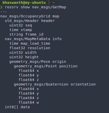
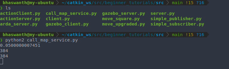
Creating a Service Client
This Service Client will call the /static_map service in order to get the map data, and will print the dimensions and resolution of the map.
1
2
3
4
5
6
7
8
9
10
11
12
13
14
15
16
17
#! /usr/bin/python2

import rospy
from nav_msgs.srv import GetMap, GetMapRequest

rospy.init_node('call_map')
rospy.wait_for_service('/static_map')

map_data = GetMapRequest()

srv = rospy.ServiceProxy('/static_map',GetMap)
response = srv(map_data)
print(response.map.info.resolution)
print(response.map.info.width)
print(response.map.info.height)

rospy.spin()
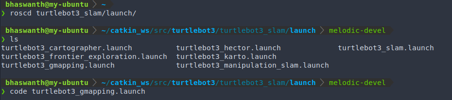
1.2.4 Creating a SLAM launch file
Till now we have used a previously created gmapping node to obtain a map of the environment. We shall now see how to create our own launch file. The main task to create this launch file is to correctly set the parameters for the turtlebot3_slam_gmapping node. This node is highly configurable and has lots of parameters that can be changed in order to improve the mapping performance. These parameters are read from the ROS Parameter Server, which can be set either in the launch file itself or in a separate YAML file.
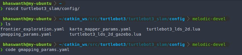
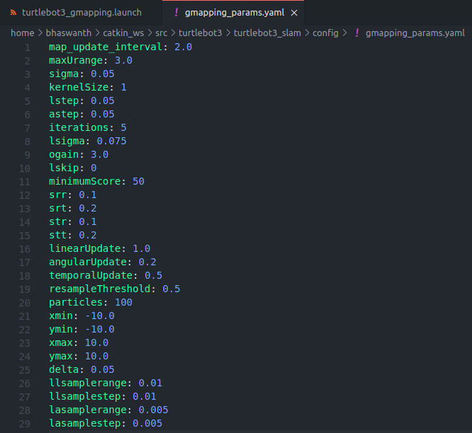
Parameters
You can refer to http://wiki.ros.org/gmapping for the list of various parameters available for the gmapping package.
1.3 Localization
In the previous section, we have seen how to obtain a map of the given environment using the robot’s sensor data. When the robot uses this map to navigate, it is necessary for it to know its position withing the map, and its orientation as well. Determining the location and pose of a robot by using its sensor readings is known as Localization.
1.3.1 Monte Carlo Localization
Monte Carlo Localization (MCL) or particle filter localization is an algorithm used by robots to localize themselves in an environment. As the robot navigates the environment, the algorithm generates random guesses (called particles) about the next possible position of the robot. As the robot gathers more sensor data, the algo discards particles that don’t match with the readings and generates more particles closer to the probable sensor readings. So the more the robot moves, the more data we get from the sensors and the more precise is the localization.
Read more
https://en.wikipedia.org/wiki/Monte_Carlo_localization
https://in.mathworks.com/help/nav/ug/monte-carlo-localization-algorithm.html
1.3.2 amcl package
The AMCL (Adaptive Monte Carlo Localization) package provides the amcl node which uses the MCL algorithm to track the localization of the robot in 2D space. The node subscribes to the laser data and transformations of the robot, and publishes the estimated position of the robot in the map. On startup, the amcl node initializes its particle filter according to the parameters provided.
Launch gazebo -
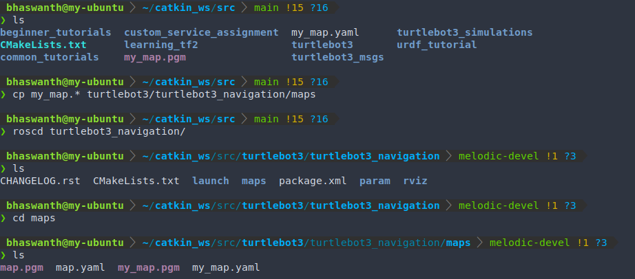
roslaunch turtlebot3_gazebo turtlebot3_house.launchWe have previously saved the map of the gazebo-house environment in
catkin_ws/src. In order to use a previously existing amcl node with turtlebot3 on our map, we need to copy the saved map into the directory in which the amcl node is located.![]()
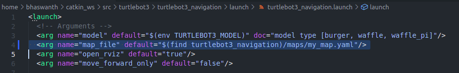
Open the relevant launch file using the command
code ~/catkin_ws/src/turtlebot3/turtlebot3_navigation/launch/turtlebot3_navigation.launchand change the map name in line 4 frommap.yamltomy_map.yaml.![]()
Save the launch file, do
catkin_makeand source your workspace.Now to launch the amcl node with gazebo running, use the command
roslaunch turtlebot3_navigation turtlebot3_navigation.launch


Rviz:
On entering the above commands, you will see something like this.

For now, you can remove a few of the displays and keep only the ones shown in the image below.

In order to visualize localization, we use the PoseArray display. Using the 2D Pose Estimate Tool, set an approximate initial position and orientation for the robot on Rviz (need not be accurate).
On moving your robot around using your keyboard, you will notice that the particle cloud shrinks in size due to the scan data allowing amcl to refine its estimate of the robot’s pose.

Topics:
- The initial pose set up using the 2D Pose Estimate tool on Rviz is published into the /initialpose topic.
- The amcl node read data published into the /scan topic (laser readings), /map topic and /tf topic, and published the estimate pose of the robot into the /amcl_pose and /particlecloud topics.


1.3.3 Services
The amcl node provides the following services:
- /global_localization (std_srvs/Empty): amcl node provides this service wherein all particles are dispersed randomly throughout the free space in the map.
- /static_map (nav_msgs/GetMap): when called, this service is used to retreive map info for localization


When you call the /global_localization service, you see something like this on Rviz. Syntax: rosservice call /global_localization "{}"

Creating a Service Server
Code for a service server that returns the position and orientation of the robot at the moment when the service is called.
1
2
3
4
5
6
7
8
9
10
11
12
13
14
15
16
17
18
19
20
21
22
23
24
#! /usr/bin/python2

import rospy
from geometry_msgs.msg import PoseWithCovarianceStamped
from std_srvs.srv import Empty, EmptyResponse

bot_pose = PoseWithCovarianceStamped()

def serv_func(req):
    print("Pose:")
    print(bot_pose)
    return EmptyResponse()


def sub_func(msg):
    global bot_pose
    bot_pose = msg.pose.pose

rospy.init_node('service_server')

srv = rospy.Service('my_pose_service',Empty,serv_func)
sub = rospy.Subscriber('/amcl_pose',PoseWithCovarianceStamped,sub_func)

rospy.spin()

Creating a Service Client
Code for a service client which performs a call to the /global_localization service in order to disperse the particles.
1
2
3
4
5
6
7
8
9
10
11
12
13
14
#! /usr/bin/python2

import rospy
from std_srvs.srv import Empty, EmptyRequest

rospy.init_node('client_global_localization')
rospy.wait_for_service('global_localization')

req = EmptyRequest()

srv = rospy.ServiceProxy('global_localization',Empty)
result = srv(req)

rospy.spin()

1.3.4 Creating a launch file
Till now we have used a previously created amcl node (slightly modified) to obtain a map of the environment. We shall now see how to create our own launch file. As mentioned before, the main task to create a launch file is to correctly set the parameters for the amcl node.


The basic structure of the launch files will be the same as shown above. All you have to do is change the parameters to obtain different outputs.
Parameters
You can refer to http://wiki.ros.org/amcl for the list of various parameters available for the amcl package.
1.4 Path Planning
1.4.1 move_base package
The move_base package provides the move_base node, which is one of the most important elements of the ROS Navigation Stack that links all processes that take place in the navigation process. The main function of the move_base node is to move the robot from the current position to the target position. It is an implementation of a Simple Action server.
Launch gazebo -
roslaunch turtlebot3_gazebo turtlebot3_house.launchWe now need to make a few small changes to a previously existing launch file. To do so, first go to the ROS directory
turtlebot3_navigation, and open the launch fileturtlebot3_navigation.launchpresent under thelaunchfolder.![]()
After that, uncomment the following lines in the code
![]()
Save the file, go back to your ROS Workspace, do a
catkin_makeand source your workspace.Now with gazebo running, launch the file containing the required move_base node using the command
roslaunch turtlebot3_navigation turtlebot3_navigation.launch.


Rviz:

Using the 2D Nav Goal tool you can goals to your robot, instructing it to move to a particular location in the map.

Topics:
The goals are sent to the robot using the 2D Nav Tool on Rviz through the /move_base/goal topic.


On doing a rostopic echo on the above mentioned topic, we can listen to the messages being published through it. Initially, when no messages are being published, we do not see anything. But if we send a target location to the robot using the 2D Nav Tool on Rviz, we get a message of the following type

We can now send goals to the robot directly, without using Rviz, using the command rostopic pub /move_base/goal move_base_msgs/MoveBaseActionGoal <parameters>.
Other relevant topics:

When the move_base node receives a goal pose, it links other components such as the global planner, local planner, recovery behaviours, and costmaps, and generates an output which is a velocity command with the message type geometry_msgs/Twist, and sends it to the /cmd_vel topic in order to move the robot.
1.4.2 Actions
As mentioned before, the move_base node is an implementation of an Action Server. This makes it possible for us to send goals, receive feedback and results, and even cancel a goal if necessary. The action server takes a goal pose with the message type geometry_msgs/PoseStamped. This allows us to send goals to the server using a simple Action Client.
The Action server provides the topic move_base/goal, which is the input of the navigation stack, and uses this topic to provide the goal pose.
Action Client
Ex 4.4
1.4.3 Creating a launch file
We shall now see how to create our own move_base launch file. This node also has a lot of parameters associated with it that can be configured.


Parameters
You can refer to http://wiki.ros.org/move_base for the list of various parameters available for the move_base package.
1.4.4 The Global Planner
Whenever a new goal is received by the move_base node, the goal messages are also sent to the global planner. The lobal planner is responsible for calculating a safe path in order to arrive at the goal pose. This path is calculated before the robot starts moving, so it will not take into account the sensor data of the robot while moving.
There are different types of global planners that different robots use to navigate an environment. Some of the important global planners are:
Navfn
The Navfn planner is one of the most commonly used global planners in the ROS Navigation Stack. It uses the Djikstra’s algorithm to calculate the shortest path between the initial and target pose of the robot.
Reference: https://github.com/ros-planning/navigation/tree/melodic-devel/navfn
Global Planner
The global planner is a more flexible replacement to the Navfn planner. It allows you to change the algorithm used for path planning (Djikstra’s in case of Navfn). These options include support for A*, toggling quadratic approximation, and toggling grid path.
Reference: https://github.com/ros-planning/navigation/tree/melodic-devel/global_planner
Carrot Planner
The Carrot planner takes the goal pose and checks if this goal is an obstacle. If it is an obstacle, it walks back along the vector between the goal and the robot until a goal point where the obstacle is not found. This planner is useful if you require your robot to move close to the given goal, even if the goal is unreachable.
Reference: https://github.com/ros-planning/navigation/tree/melodic-devel/carrot_planner
1.4.5 The Local Planner
Once the global planner has calculated the path to follow, this path is sent to the local planner. The local planner will then execute each segment of the global plan. With the help of the plan provided by the global planner and a map, the local planner will send velocity commands in order to move the robot.
The local planner monitors the odometry and laser data from the robot and chooses a collision-free local plan. It can recompute the robot’s path while it is moving in order to keep the robot from colliding with obstacles.
base_local_planner
The base_local_planner provides an implementation of the Trajectory Rollout and Dynamic Window Approach (DWA). The basic idea of how the algorithm works is as follows:
- Samples the robot space.
- For each sampled velocity, it performs simulations to predict the outcomes when the sampled velocity is applied.
- It evaluates the trajectory resulting from the simulation and discards the unwanted trajectories.
- It picks the best trajectory and sends the associated velocity commands for the robot to move
Trajectory Rollout samples are from a set of achievable velocities ove the entire simulation, while DWA samples are from the set of achievable velocities for just one simulation step.
dwa_local_planner
The dwa_local_planner provides an implementation of the Dynamic Window Approach (DWA) algorithm. It is basically a cleaner version of the base local planner’s DWA option.
You can find the list of parameters associated with the DWA planner here.
1.4.6 Costmaps
A costmap is a map that represents place that are safe for the robot to be in a grid of cells. Unusally the values in the costmap are binary, representing either free space orplaces where the robot would be in collision. Each cell in a costmap has an integer value in the range {0,255}.
- 255 (NO_INFORMATION): Cells that do not contain enough information
- 254 (LETHAL_OBSTACLE): Indicates presence of obstacle in a cell
- 253 (INSCRIBED_INFLATED_OBSTACLE): Indicates no obstacle but moving the robot to this location will result in a collision
- 0 (FREE_SPACE): No obstacle in the cell
There are 2 types of costmaps:
- Global Costmap - created from static map
- Local Costmap - created from sensor readings
Costmap parameters are defined in 3 different files:
- A YAML file that sets the parameters for the global costmap - global_costmap_params.yaml
- A YAML file that sets the parameters for the local costmap - local_costmap_params.yaml
- A YAML file that sets the parameters for both the global and local costmaps - costmap_common_params.yaml
Global Costmap
The global costmap is created from a user-generated static map and is used by the global planner. It is initialized to match the width, height, and obstacle information provided by the static map.
The global costmap has its own set of parameters defined in a YAML file.

See Parameters section of http://wiki.ros.org/costmap_2d
Local Costmap
The local costmap is created from the sensor readings taken from the robot and is used by the local planner.
The local costmap too has its own set of parameters defined in a YAML file.
