

Abstract
Sophisticated robots operating in an underwater environment require vision to perform different tasks. This project involves developing a reliable vision system by employing a depth camera, rather than a conventional binocular-stereo camera, for underwater depth estimation and localization. The project’s initial phase, until midsemester, consisted of testing the depth camera’s ability to estimate depth in the air. This report covers the second phase of the project, which involves underwater experimentation with objects for depth measurements.
DEPTH ESTIMATION AND LOCALIZATION
Camera Calibration
Camera calibration is the process of estimating the parameters of a lens and camera image sensor. These calibrated camera parameters can be used to rectify the image by correcting lens distortion, estimating the depth of objects, and localization of the camera in the environment.
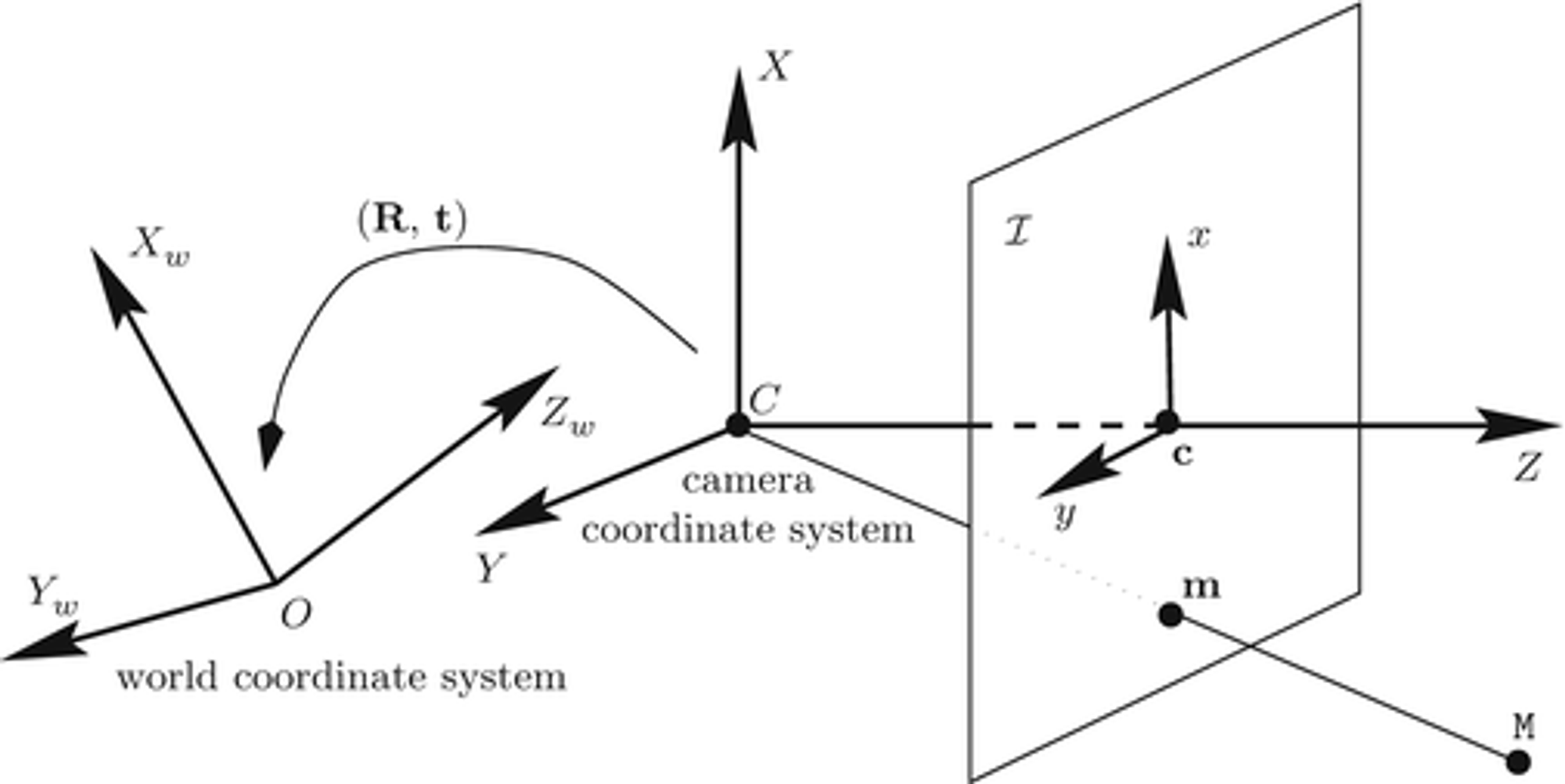
The camera parameters, given by a camera matrix, includes the intrinsic, extrinsic and distortion parameters of the camera. The 3D world coordinates of the objects and their corresponding 2D image points are required to compute the camera matrix.
The following are the components of the camera calibration matrix:
- Intrinsic parameters - The camera internal parameters such as the focal length, optical center, and the skew coefficient.
- Extrinsic parameters - The pose parameters of the camera given by a rotation and a translation vector.
- Distortion parameters -
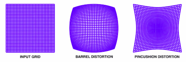
- Radial distortion - When light rays bend differently near a lens’s edges and in its optical center, the result is radial distortion. The radial distortion coefficients model this type of distortion.
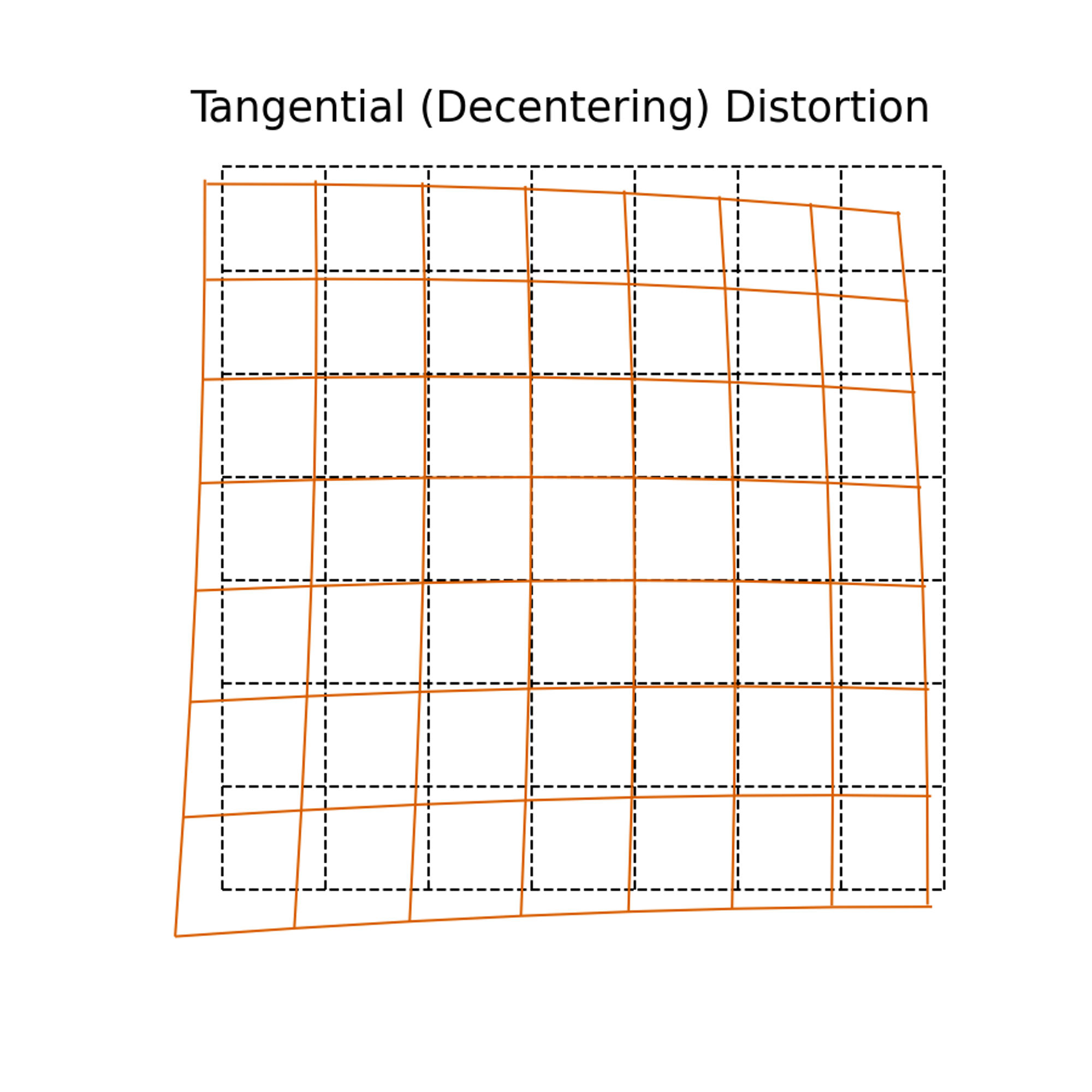
- Tangential distortion - Occurs when the lens and the image plane are not parallel. The tangential distortion coefficients model this type of distortion.
![Untitled]()

Radial distortion:
\[\begin{aligned}& x_{\text {corrected }}=x\left(1+k_1 r^2+k_2 r^4+k_3 r^6\right) \\& y_{\text {corrected }}=y\left(1+k_1 r^2+k_2 r^4+k_3 r^6\right)\end{aligned}\]Tangential distortion:
\[\begin{aligned}& x_{\text {corrected }}=x+\left[2 p_1 x y+p_2\left(r^2+2 x^2\right)\right] \\& y_{\text {corrected }}=y+\left[p_1\left(r^2+2 y^2\right)+2 p_2 x y\right]\end{aligned}\]where, $x$, $y$ = undistorted pixel locations
$r^2=x^2+y^2$
$k_1,k_2,k_3 \space -$ radial distortion coefficients
$p_1,p_2 \space -$ tangential distortion coefficients
There exist quite a few methods for camera calibration, the most popular one being the Zhang Zhengyou calibration method.
Zhang’s method:
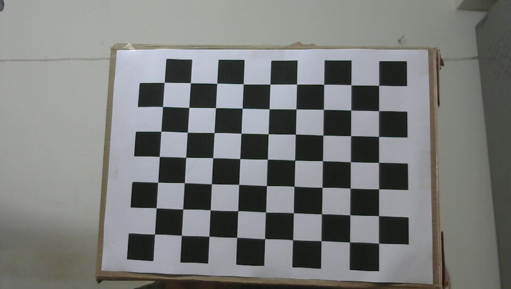
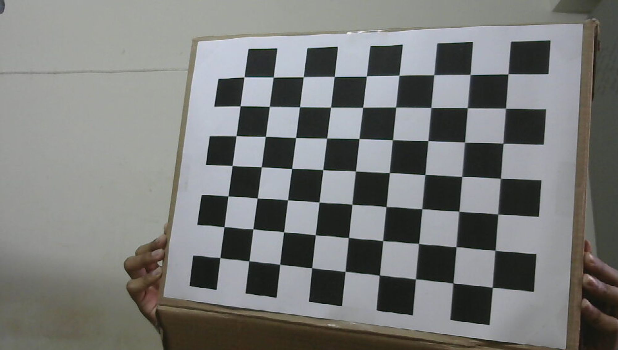
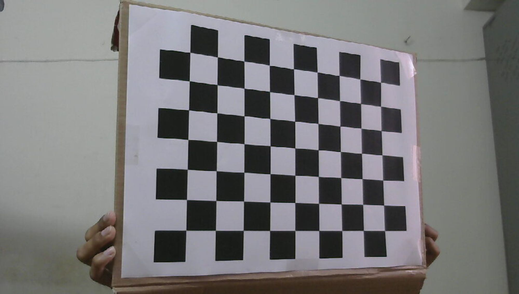
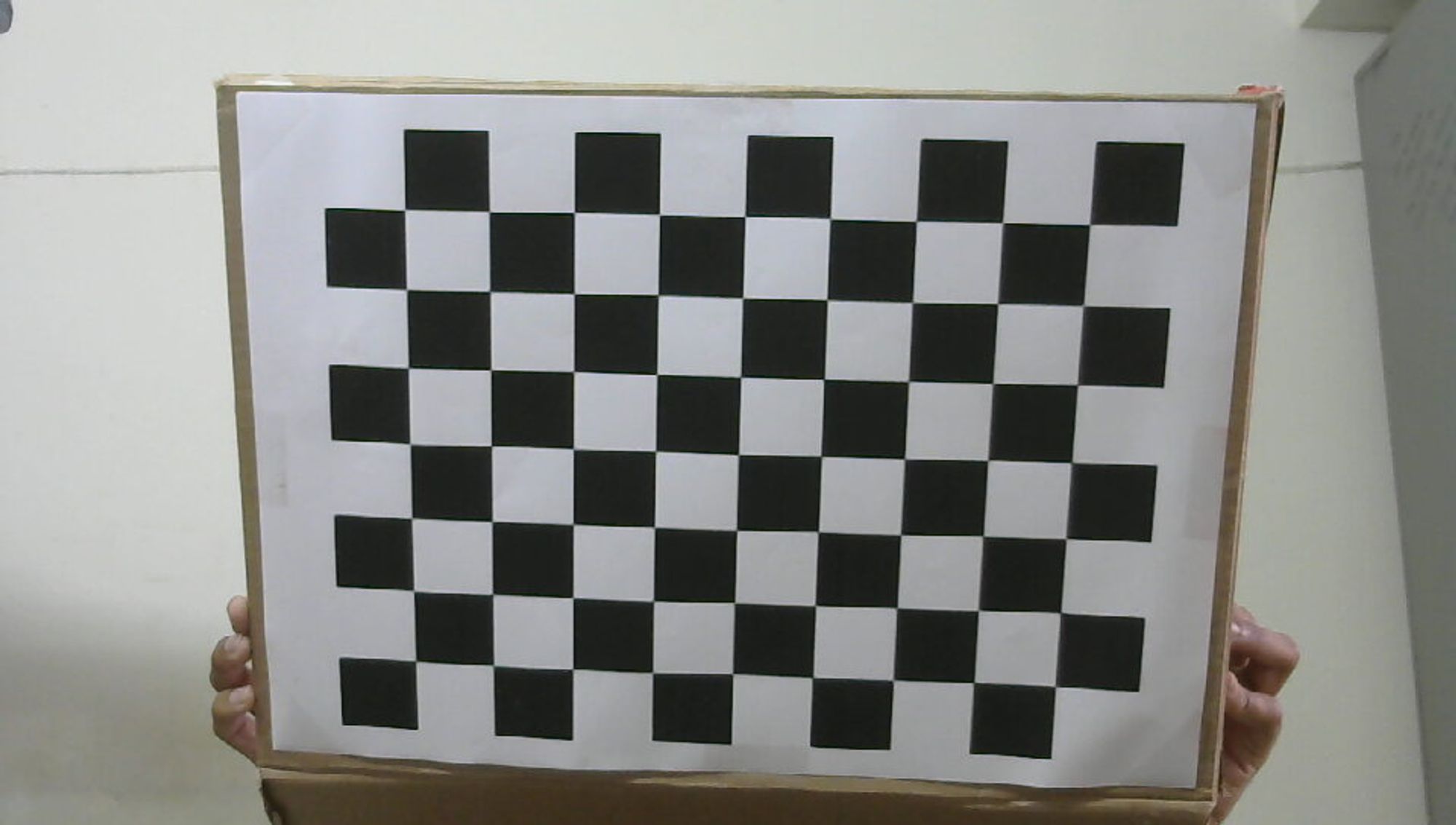
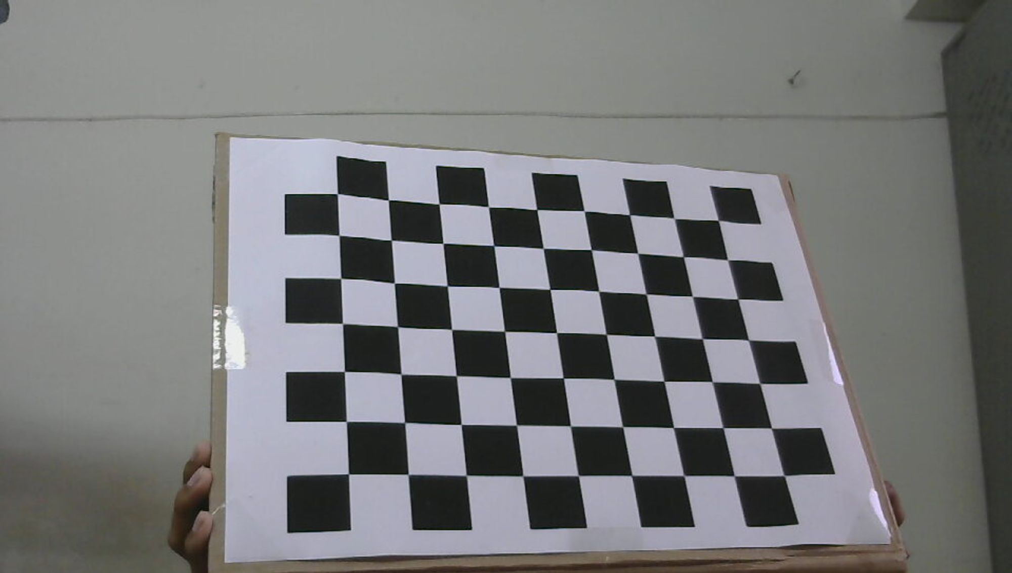
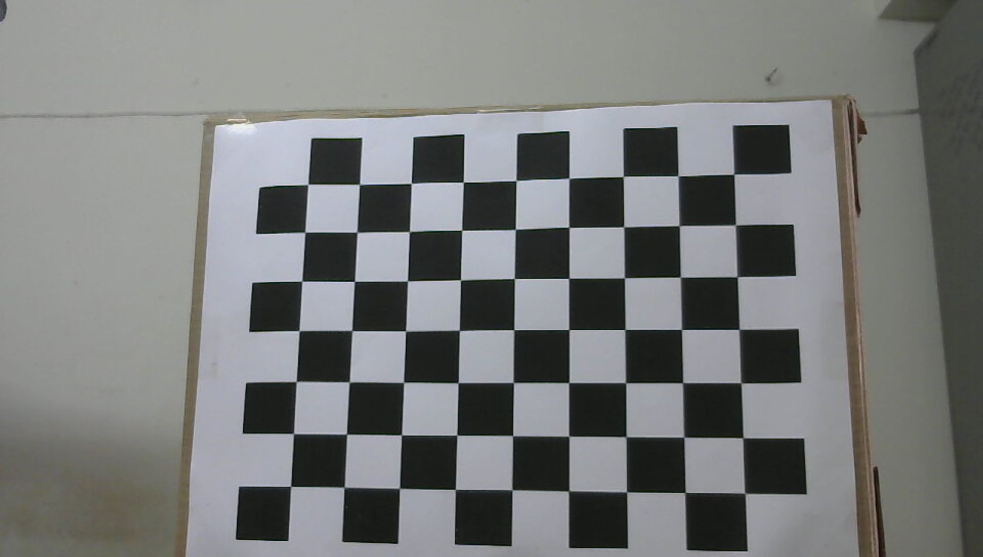
The Zhang Zhengyou technique is a calibration method that uses a checkerboard pattern. It runs a corner detector to find the points of interest and their positions on the checkerboard. The world coordinate system is set to the corner of the checkerboard, and all points are assumed to lie on the XY-plane.
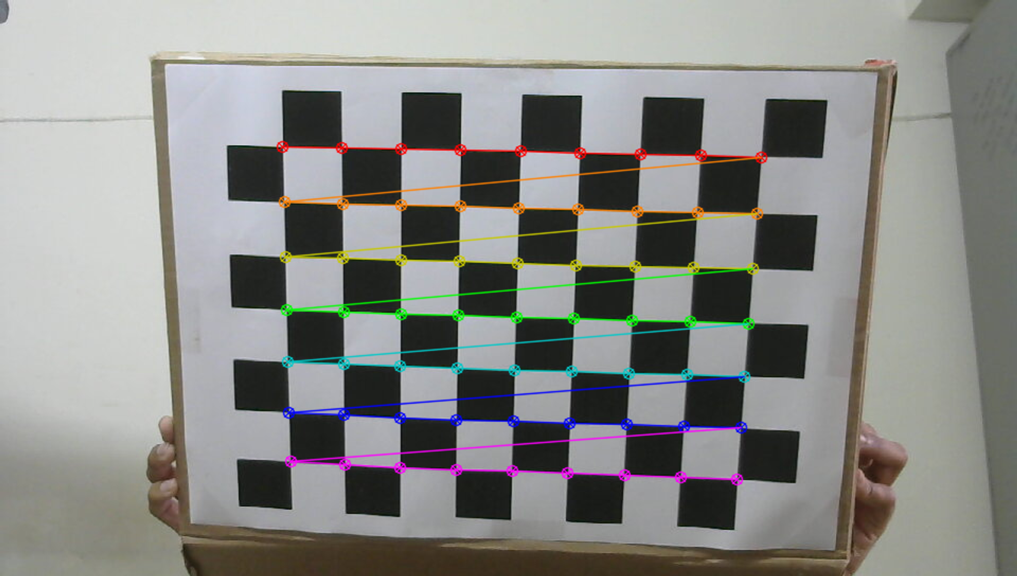
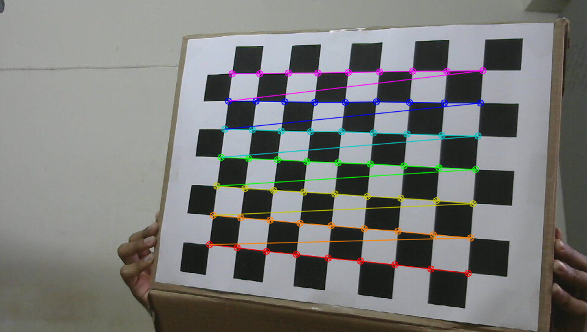
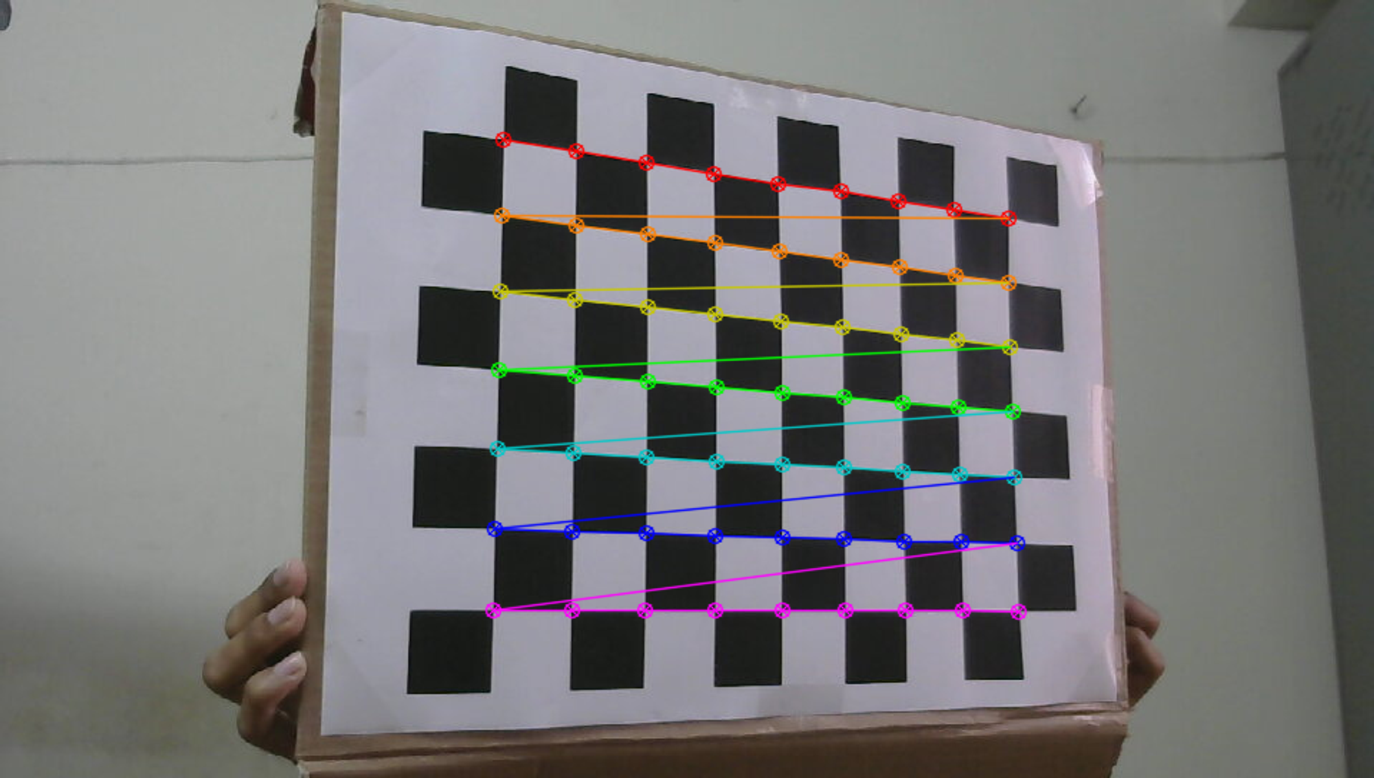
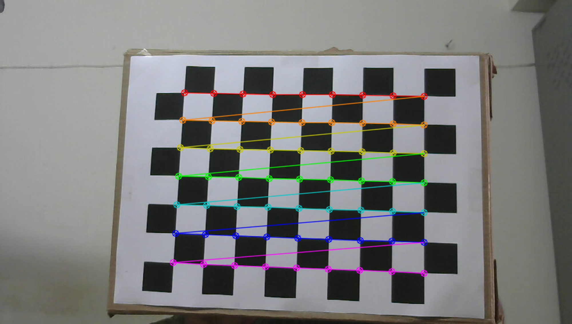
The method requires test patterns for camera calibration. The following shows the set of all test images used for calibration -
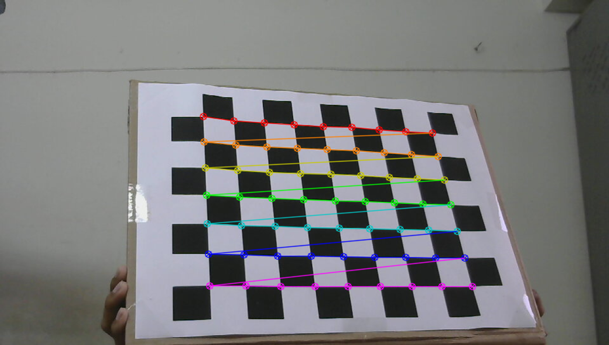
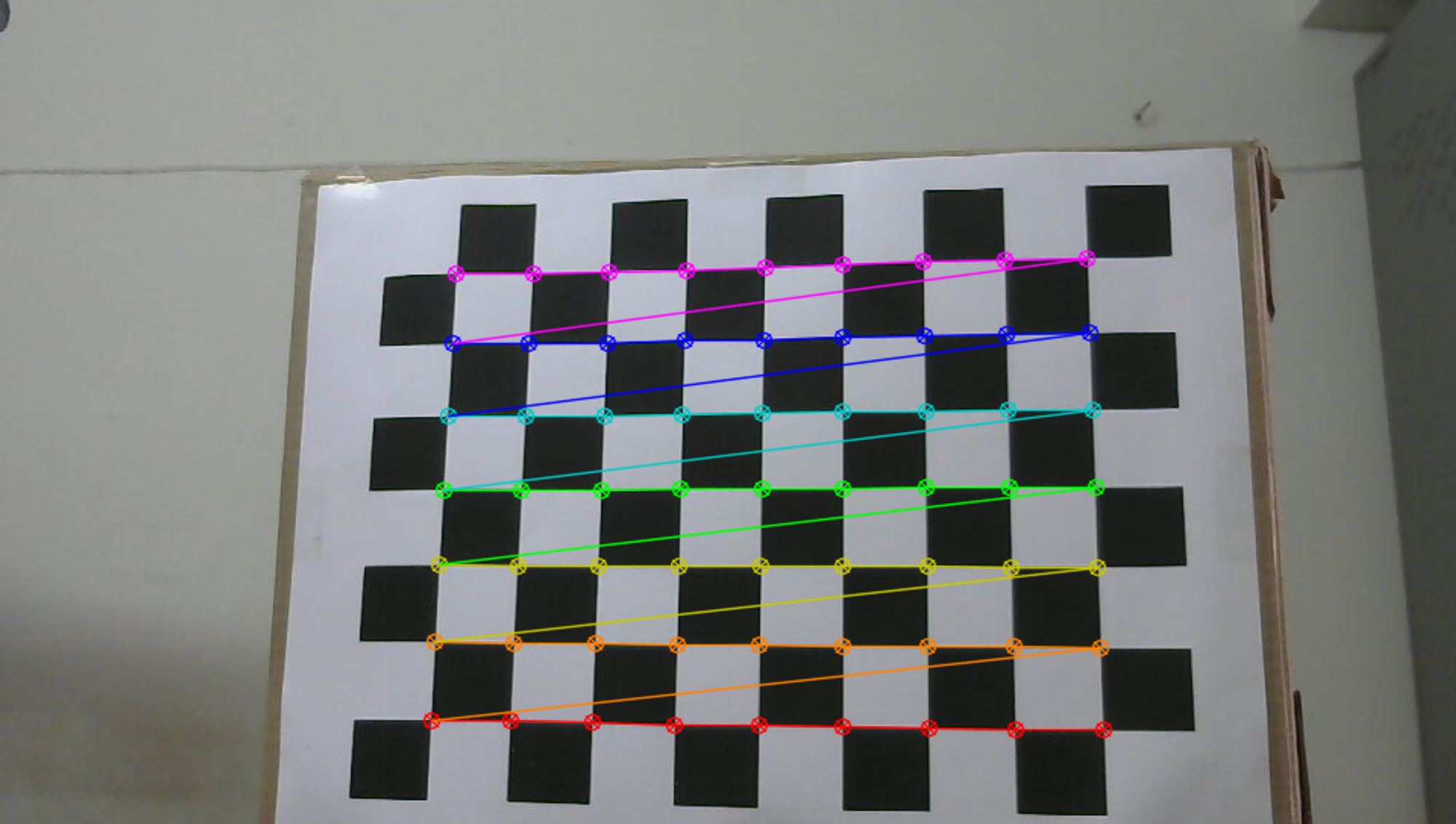
The corners of the checkerboard are found using OpenCV, as shown below.
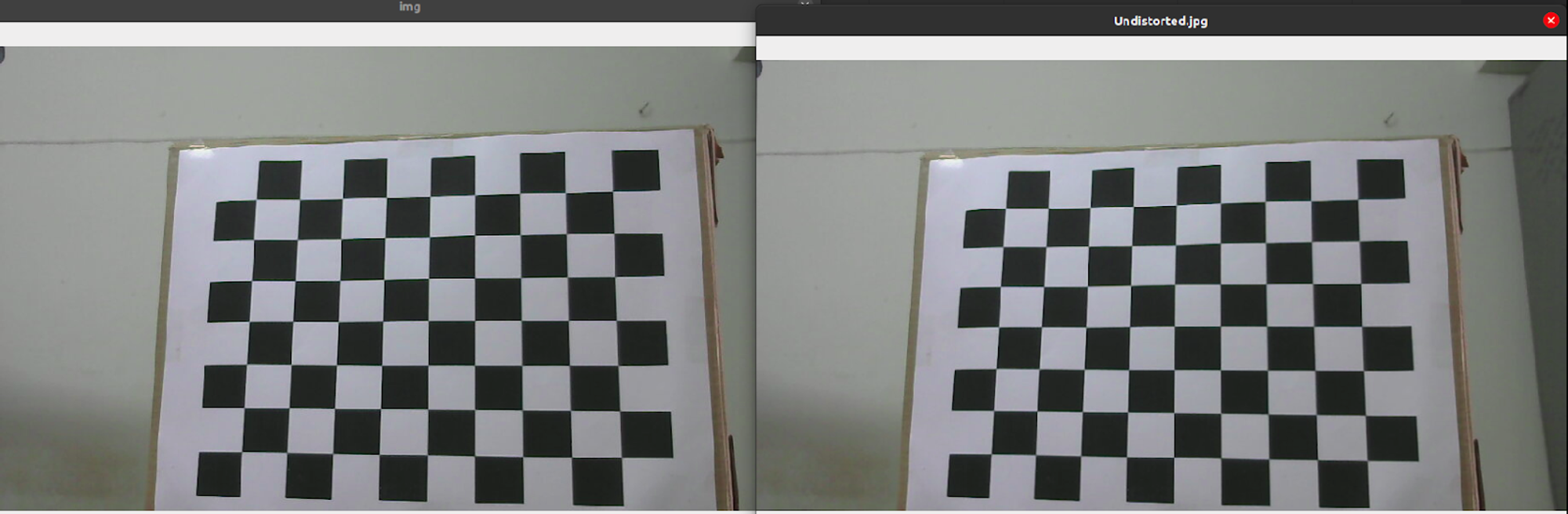
Once the calibration is done, we can take an image and undistort it. The camera matrix and the distortion coefficients can then be stored. The following are the results obtained after running the code -
Camera Matrix:
\[\begin{bmatrix} 1.07443280e+03 & 0.00000000 \mathrm{e}+00 & \quad 4.32669818 \mathrm{e}+02 \\ 0.00000000 \mathrm{e}+00 & \quad 1.01862189 \mathrm{e}+03 & \quad 2.63179677 \mathrm{e}+02\\ 0.00000000 \mathrm{e}+00 & \quad 0.00000000 \mathrm{e}+00 & \quad 1.00000000 \mathrm{e}+00\\ \end{bmatrix}\]Distortion Parameters:
\[\begin{bmatrix} -0.09265683 & 0.80628656 & -0.00354457 & -0.00947235 & -1.59645404 \end{bmatrix}\]Total Error: $0.06509290538498035$
Depth camera:
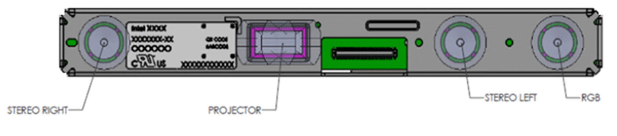
The Intel Realsense D415 Depth camera uses stereo vision to calculate depth, and consists of a pair of depth sensors, RGB sensor, and an infrared projector.
- Image sensors - The set of image sensors enable capturing of disparity between images up to 1280 x 720 resolution.
- RGB sensor - Dedicated color image signal processor for image adjustments and scaling color data.
- Infrared sensor - Active infrared projector to illuminate objects to enhance the depth data.
The camera data rectified in its Vision Processor D4 hardware component is streamed in most modes. The rectified data is then sent to the computer via the USB cable and made available for us to view. The rectified and unrectified images can be obtained by using the relevant IR stream modes, as follows -
1) Y8 IR mode - provides calibrated and rectified images.
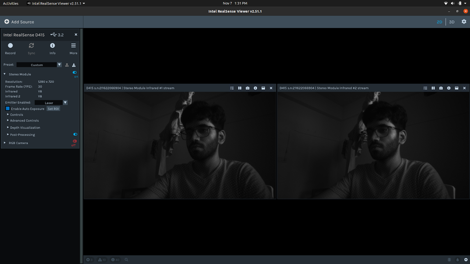
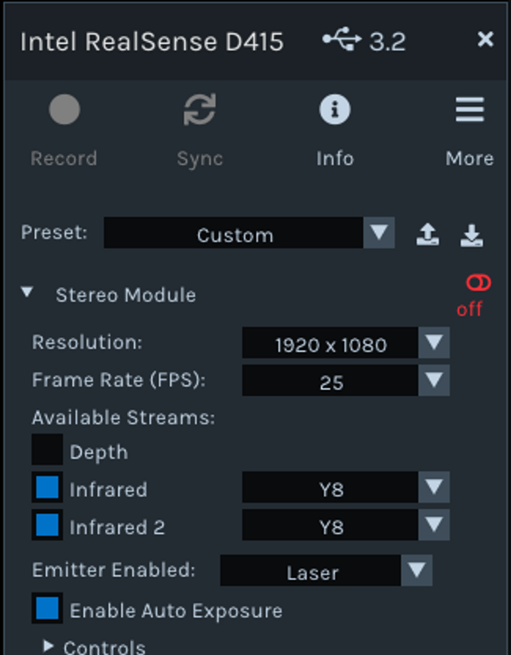
2) Y16 IR mode - provides unrectified images (closest to what you would get from a true rawstream without calibration)
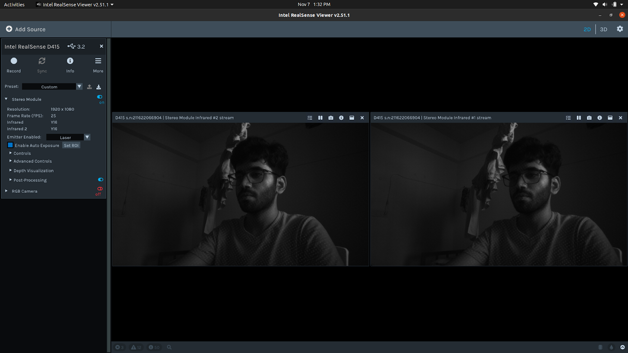
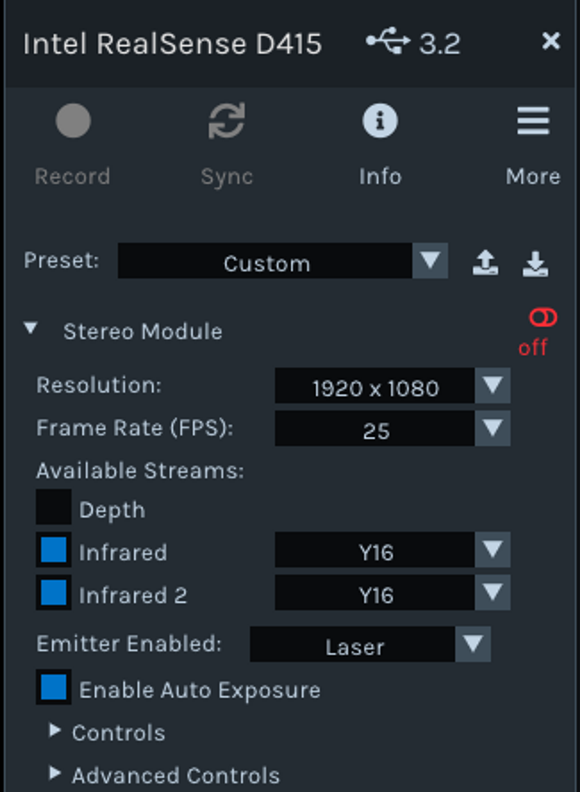
The Intel Realsense SDK, however, does not allow simultaneous RGB stream of the left and right cameras. Thus the process of camera calibration in the depth camera is done by the on-board chip, and the calibrated data can be obtained by looking into the Y8 IR mode stream. The same can also be obtained using OpenCV and the provided librealsense API, as shown below.
Depth Estimation
Using calibrated IR data:
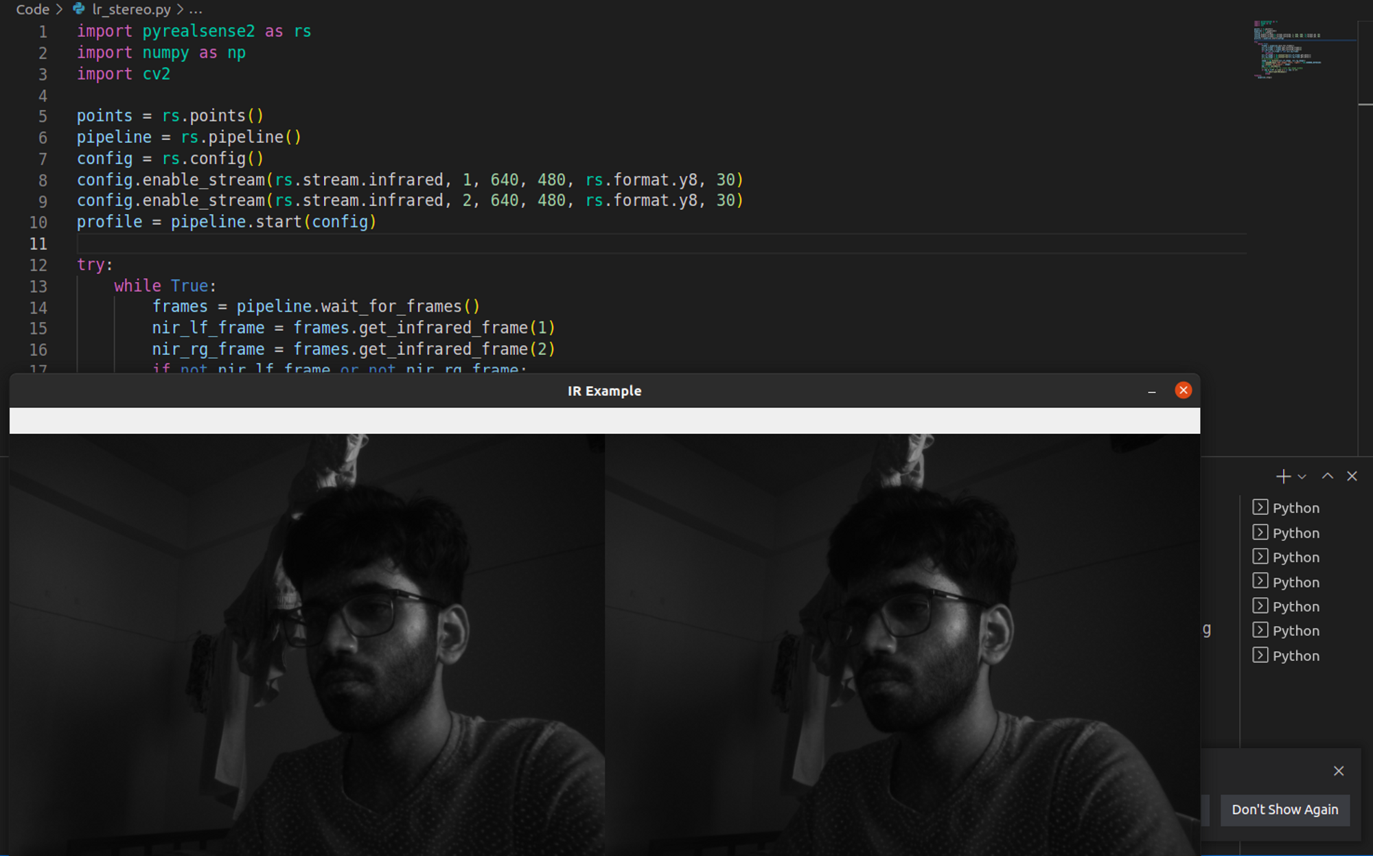
The calibrated IR image data from the depth camera can be used to perform depth estimation. The StereoSGBM class provided by OpenCV is used for computing the stereo correspondence using the Sum of Squared Differences (SSD) block-matching algorithm, and for disparity calculation by matching the blocks in left and right images as shown below.
The image below shows the left and right IR images that are used as input to the stereo-depth algorithm.
The following is the depth map, plotted on matplotlib, obtained from the stereo-depth algorithm. The map resembles the image on the right side to some extent, but needs to be improved by playing around with the values of the number of disparities and block size, which are given as input to the StereoSGBM class.
Using default calibration data:
The entire process of camera calibration, rectification, block matching, disparity calculation, and depth estimation is carried out by the On-board Chip of the Intel Realsense depth camera by default. Thus, the simpler way of performing depth estimation is by listening to the relevant streams and using them to find the depth. The depth stream, Z16 mode, and the color stream, BGR8 mode, are used for this purpose.
The image on the left below shows the color frame and the corresponding distance at the point of placement of the cursor, while the image on the right shows the depth frame.
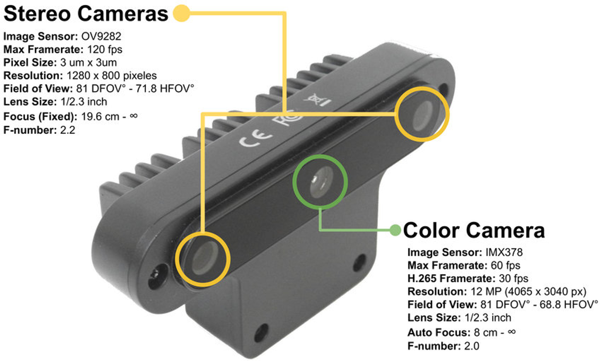
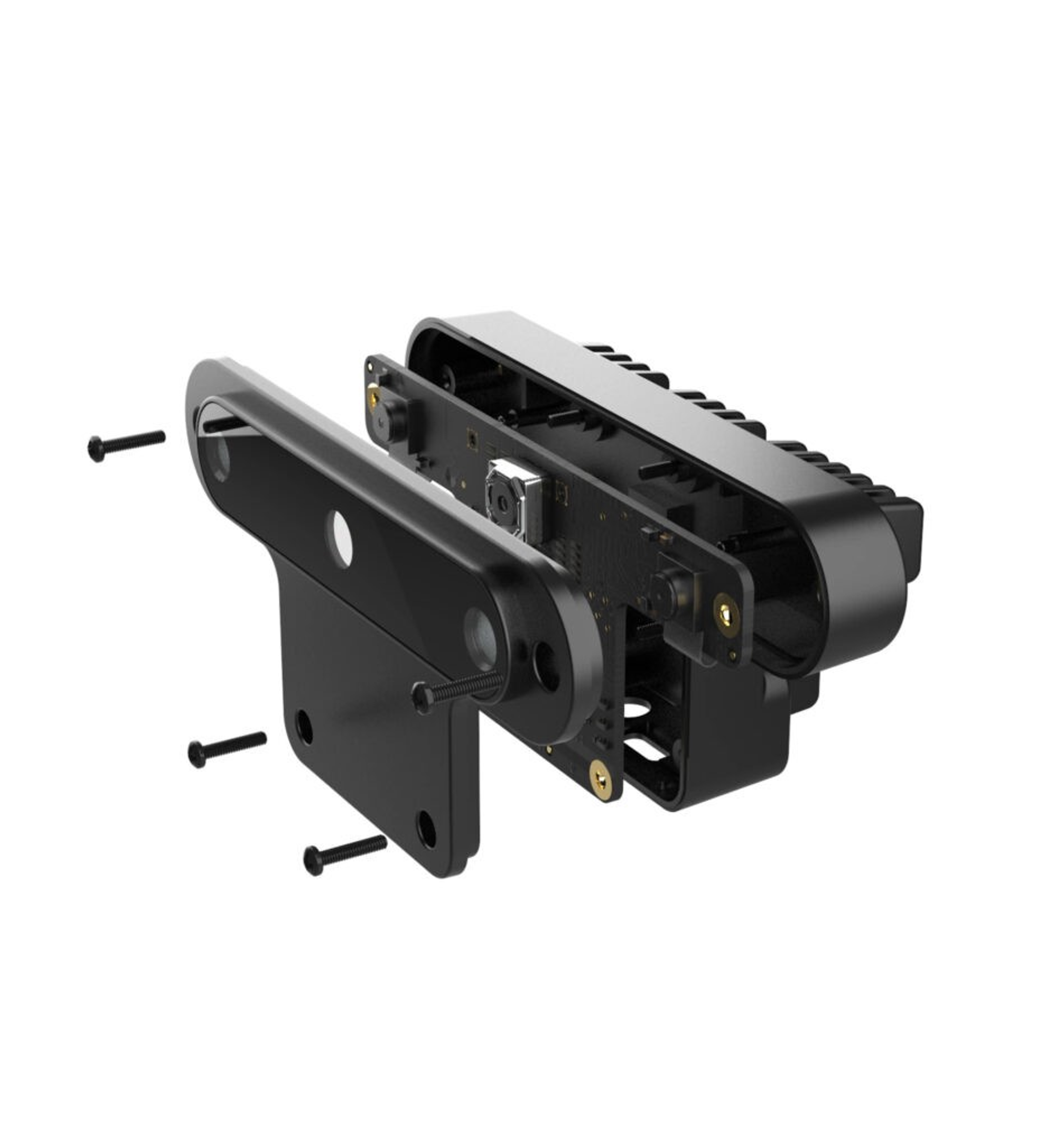
OAK-D Camera
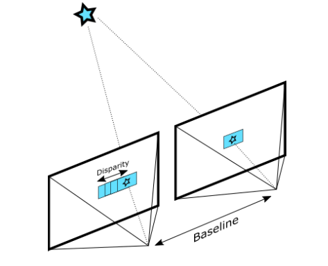
The OAK-D depth camera by Luxonis has three on-board cameras which can implement stereo and RGB vision used for depth and AI processing. The camera has a baseline length of 7.5cm, which is the distance between the left and the right stereo cameras.
- Stereo Cameras - The set of image sensors enable capturing of disparity between images up to 1280 x 800 (1MP) resolution.
- Color Camera - Dedicated color image signal processor that provides a resolution of up to 4032 x 3040 (12MP).
The camera is capable of performing stereo depth perception with filtering, post-processing, RGB-depth alignment, and high configurability.
UNDERWATER TESTING
The depth camera calibrated in the air cannot be used for performing underwater experiments due to differences in disparities caused by the refraction of light. As a result, the depth camera needs to be calibrated underwater and then used for depth estimation.
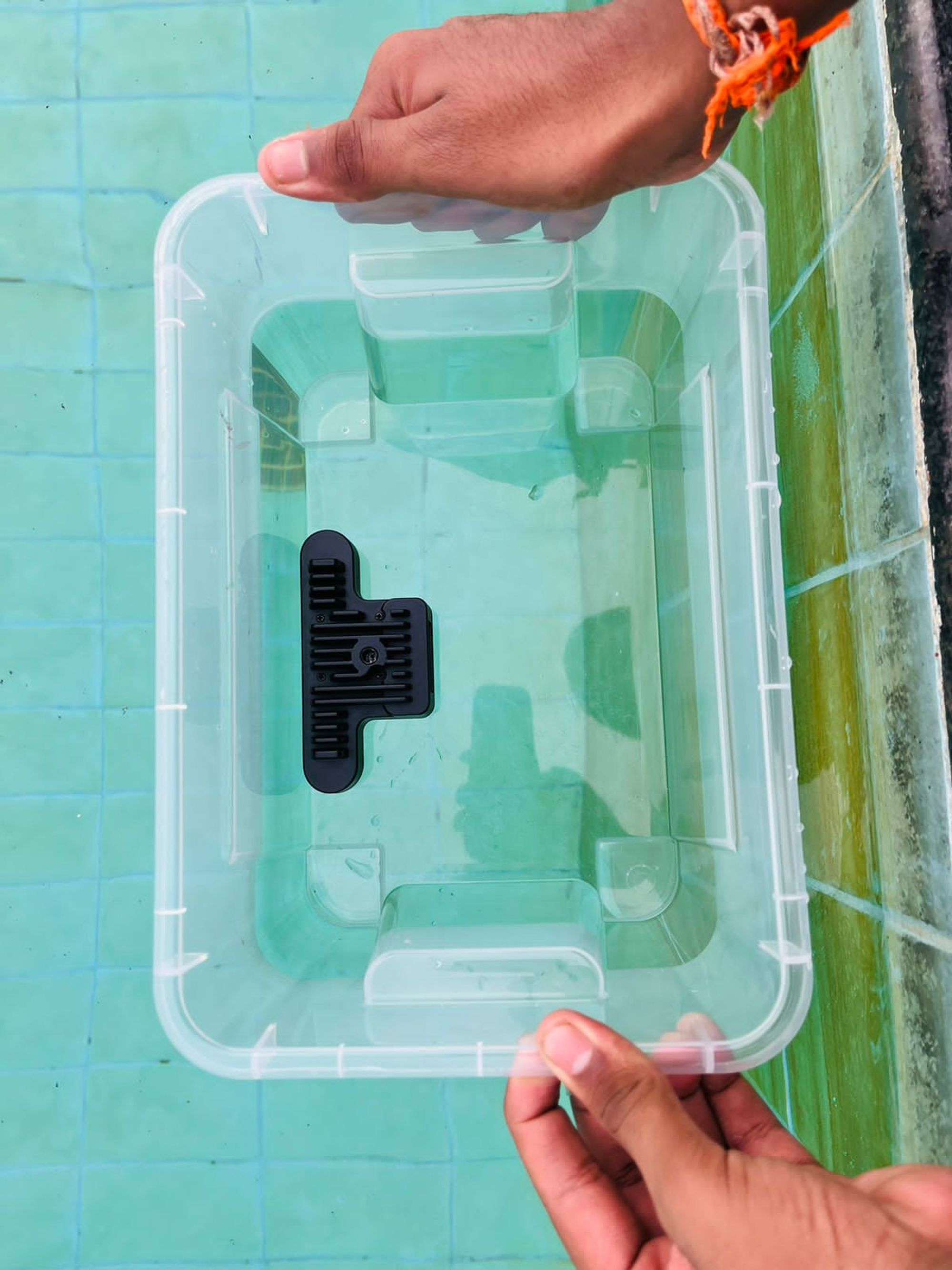
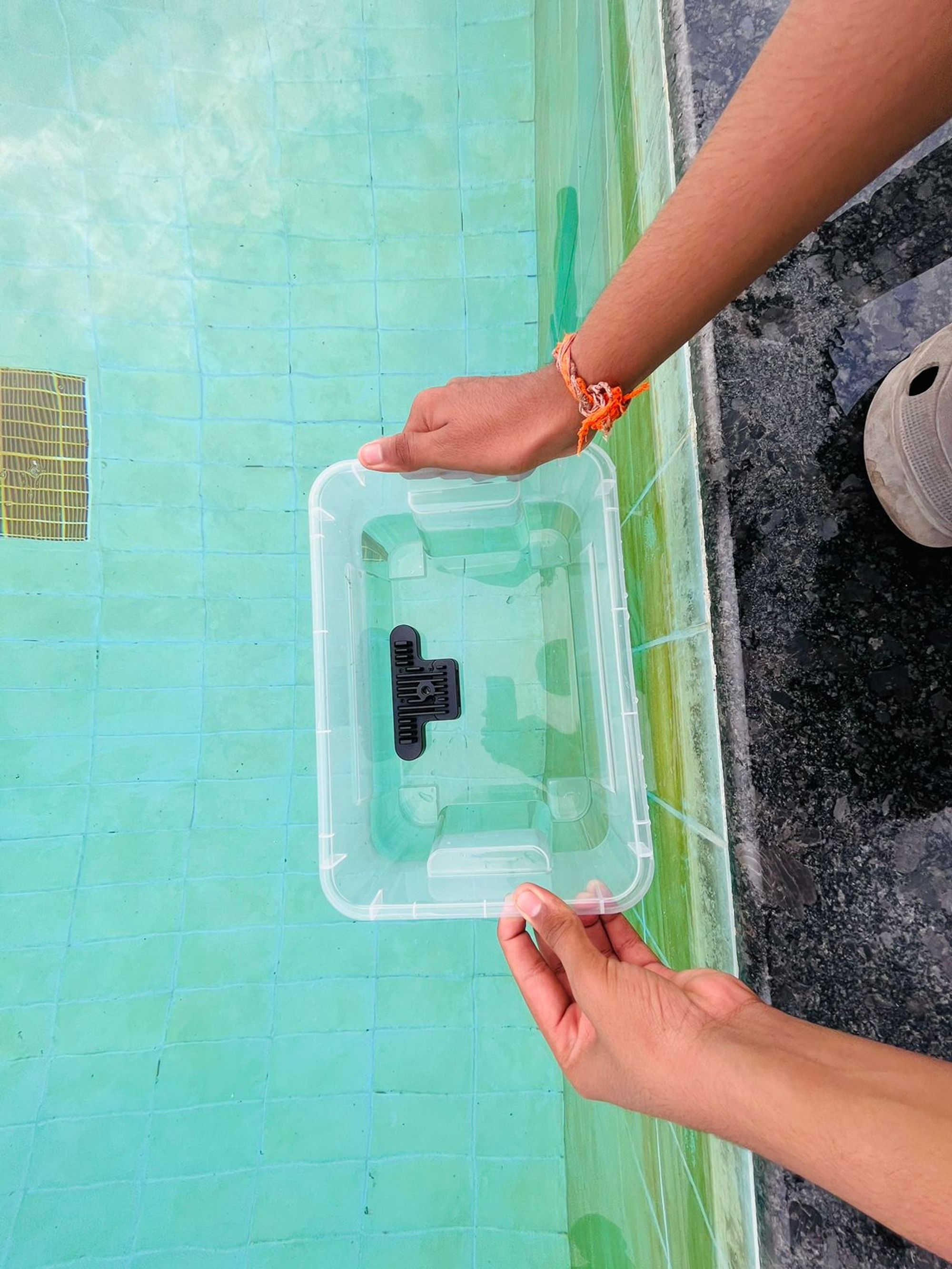
Setup
The setup to perform underwater depth measurement involves placing the OAK-D depth camera in a transparent container and holding it inside water partially submerged, as shown in the images below. The entire setup and all the experiments were performed in the swimming pool.
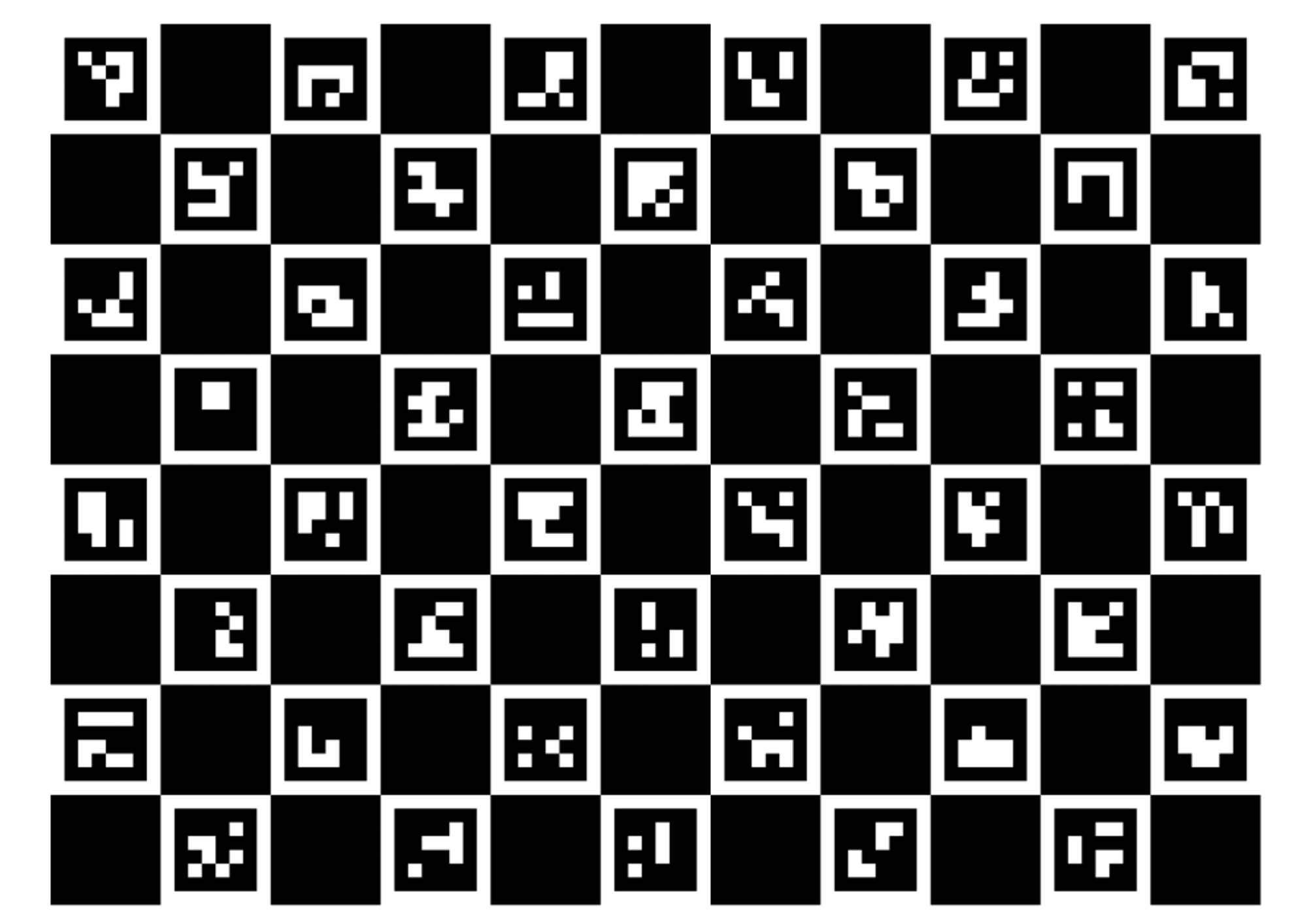
Camera Calibration
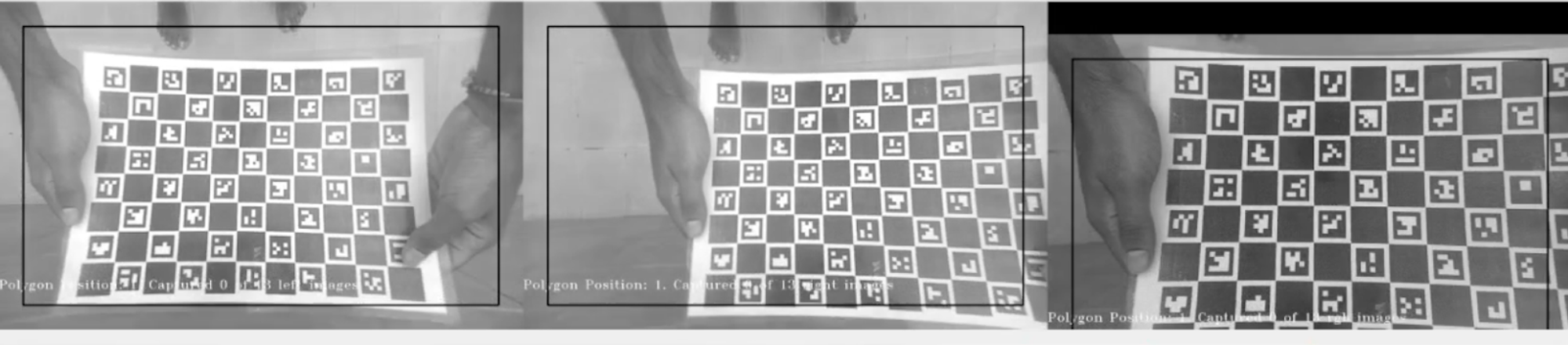
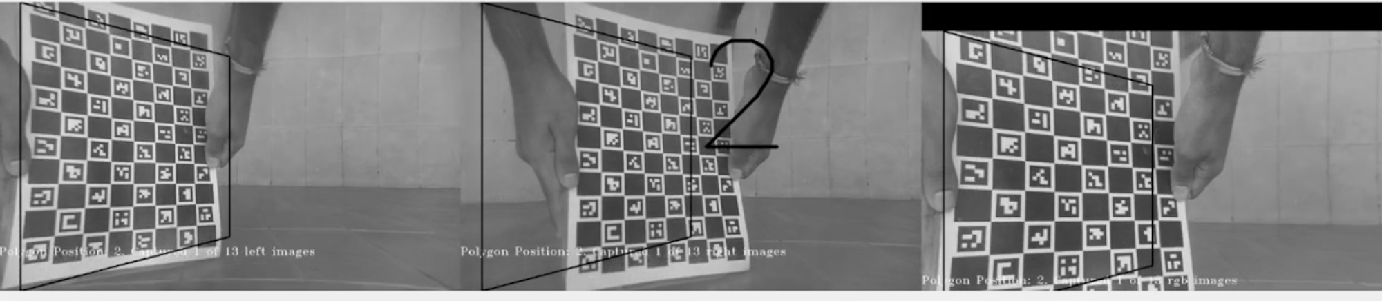
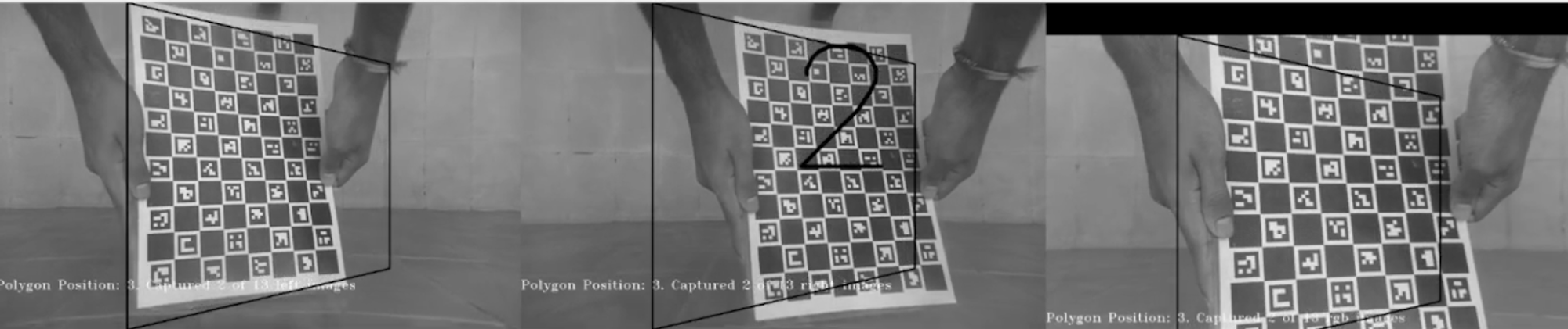
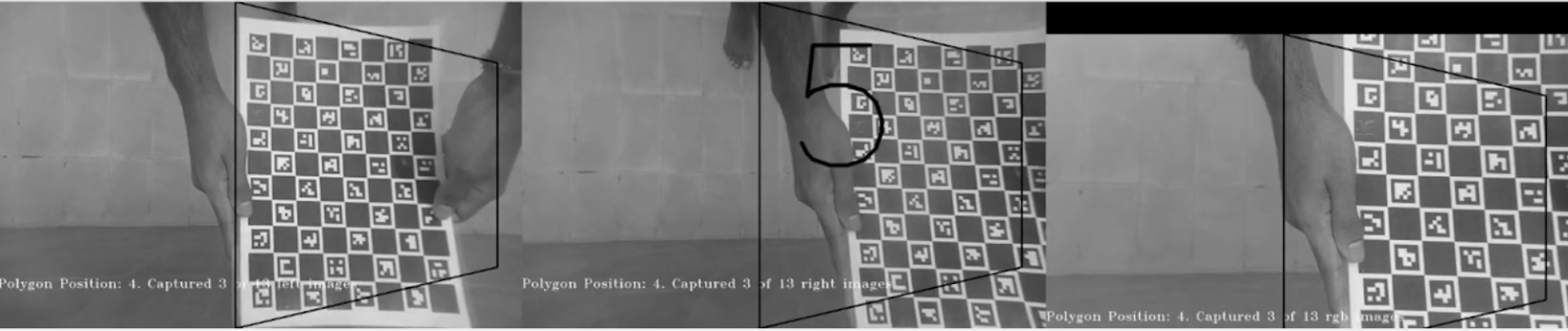
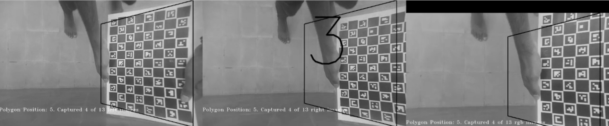
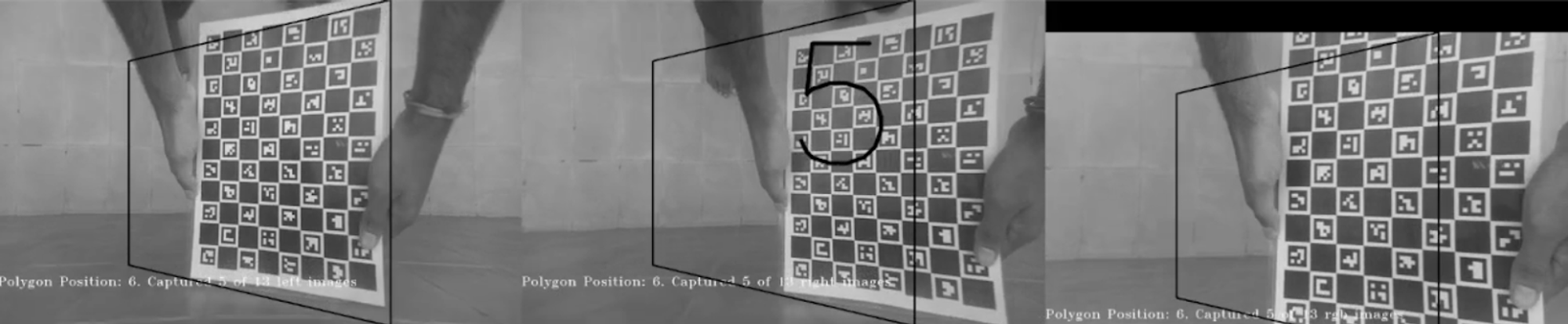
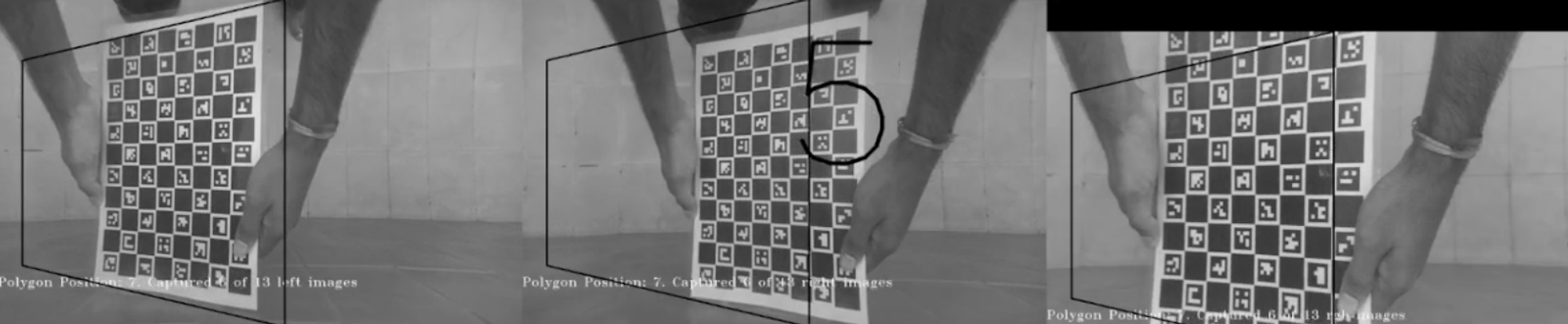
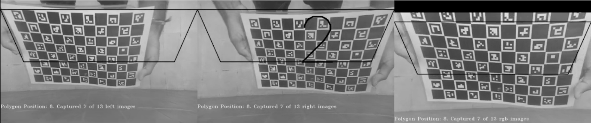
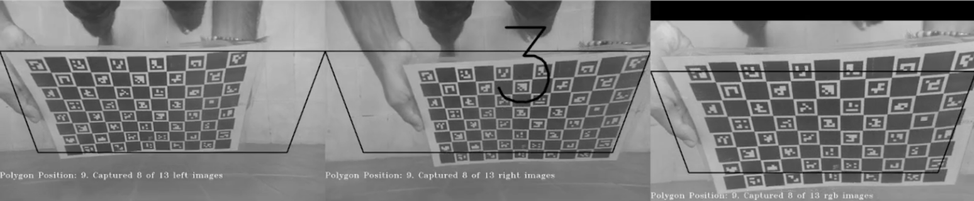
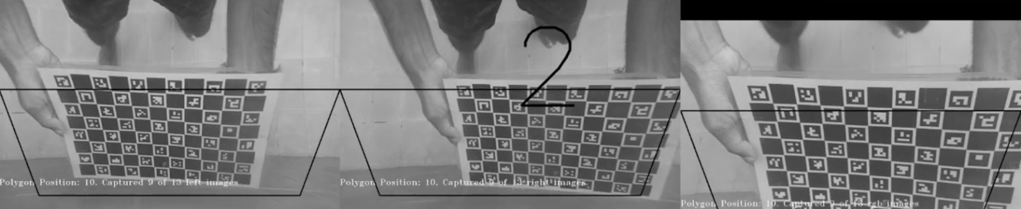
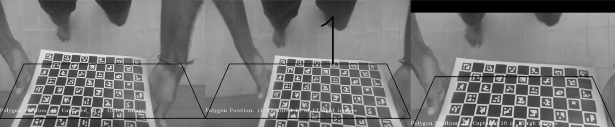
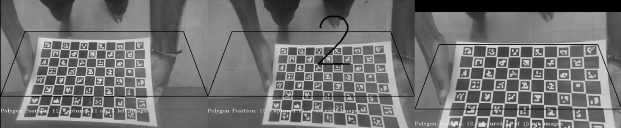
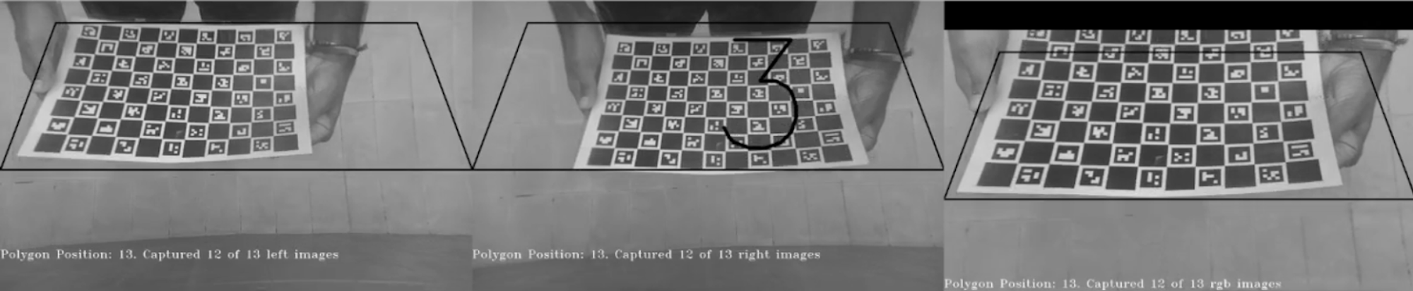
The camera is calibrated using a charuco board, in a process very similar to calibrating using the Zhang Zhengyou technique. The charuco board is printed onto a flat surface, and 13 different images are captured in different orientations.
The following shows an image of the charuco board having a square size of 2.45 cm -
The following shows the set of all test images (left + right + rgb) used for calibration. The numbers that appear on some images in the middle show the timer while capturing the image -
Once the camera calibration is complete, we obtain the distortion coefficients, intrinsic parameters, extrinsic parameters, and the stereorectification data of the camera.
1
2
3
4
5
6
7
8
9
10
11
12
13
14
15
16
17
18
19
20
21
22
23
24
25
26
27
28
29
30
31
32
33
34
35
36
37
38
39
40
41
42
43
44
45
46
47
48
49
50
51
52
53
54
55
56
57
58
59
60
61
62
63
64
65
66
67
68
69
70
71
72
73
74
75
76
77
78
79
80
81
82
83
84
85
86
87
88
89
90
91
92
93
94
95
96
97
98
99
100
"extrinsics": {
                    "rotationMatrix": [
                        [
                            0.9999324679374695,
                            -0.008666034787893295,
                            0.007746713235974312
                        ],
                        [
                            0.008631718344986439,
                            0.9999528527259827,
                            0.0044522895477712154
                        ],
                        [
                            -0.00778493145480752,
                            -0.0043851216323673725,
                            0.9999600648880005
                        ]
                    ],
                    "specTranslation": {
                        "x": -7.5,
                        "y": 0.0,
                        "z": 0.0
                    },
                    "toCameraSocket": 2,
                    "translation": {
                        "x": -7.581012725830078,
                        "y": -0.0006467599887400866,
                        "z": 0.040638044476509094
                    }
                },

"intrinsicMatrix": [
                    [
                        799.7395629882813,
                        0.0,
                        662.93359375
                    ],
                    [
                        0.0,
                        799.383056640625,
                        382.2420654296875
                    ],
                    [
                        0.0,
                        0.0,
                        1.0
                    ]
                ],

"rectifiedRotationLeft": [
            [
                0.9999605417251587,
                -0.008557096123695374,
                0.002386769512668252
            ],
            [
                0.00855177454650402,
                0.9999609589576721,
                0.0022310472559183836
            ],
            [
                -0.002405767561867833,
                -0.002210548147559166,
                0.9999946355819702
            ]
        ],
        "rectifiedRotationRight": [
            [
                0.9999856352806091,
                8.531191269867122e-05,
                -0.005360426381230354
            ],
            [
                -9.721628157421947e-05,
                0.9999975562095642,
                -0.0022205670829862356
            ],
            [
                0.005360223352909088,
                0.0022210562601685524,
                0.9999831914901733
            ]
        ],

"distortionCoeff": [
                    9.491045951843262,
                    -102.06877136230469,
                    0.0008228731458075345,
                    0.001999291591346264,
                    401.19476318359375,
                    9.264853477478027,
                    -100.42776489257813,
                    394.56182861328125,
                    0.0,
                    0.0,
                    0.0,
                    0.0,
                    0.0,
                    0.0
                ],
Depth Estimation
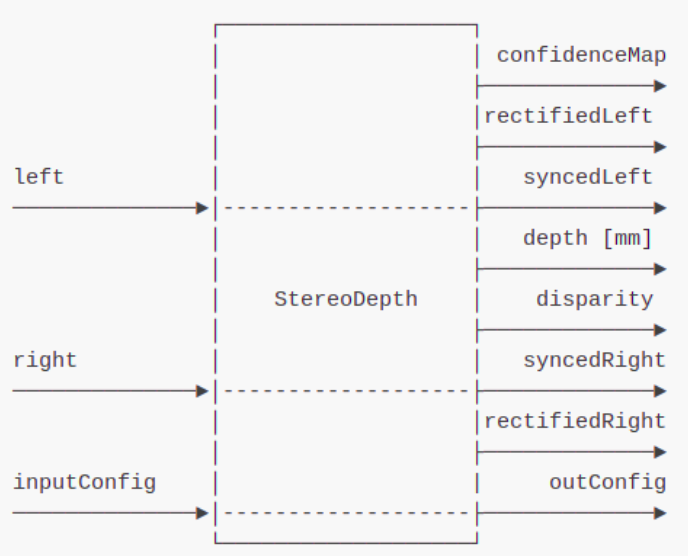
The StereoDepth node, provided by the OAK-D API, is used to calculate the disparity and depth from the stereo camera pair.
The generation of the depth map from the StereoDepth node can be visualized using the following images, which are taken in air -
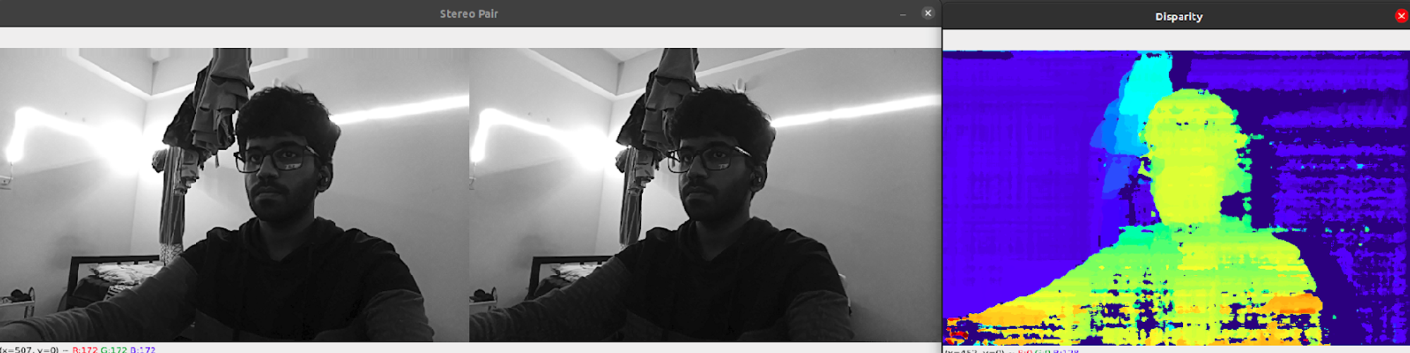
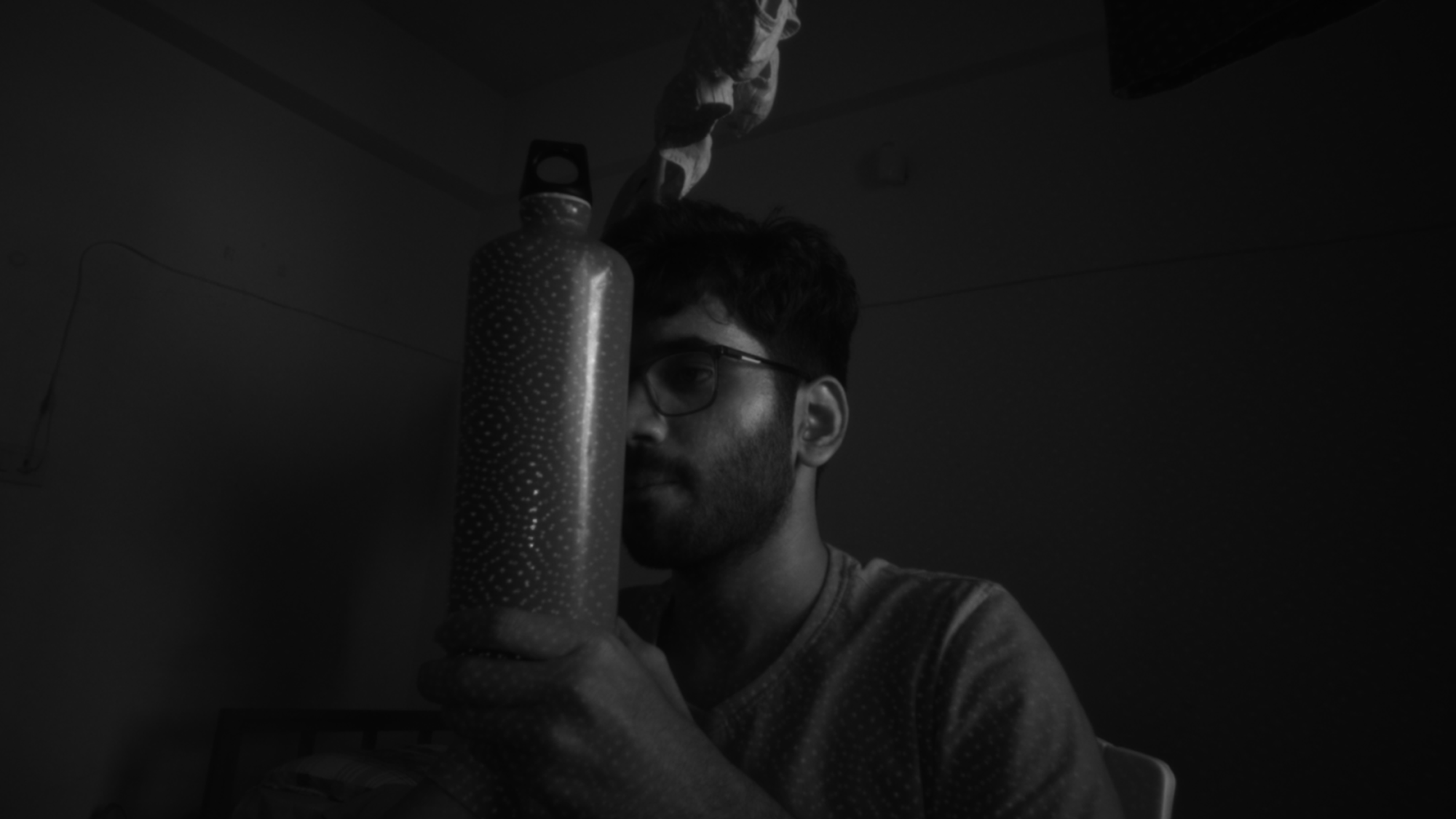
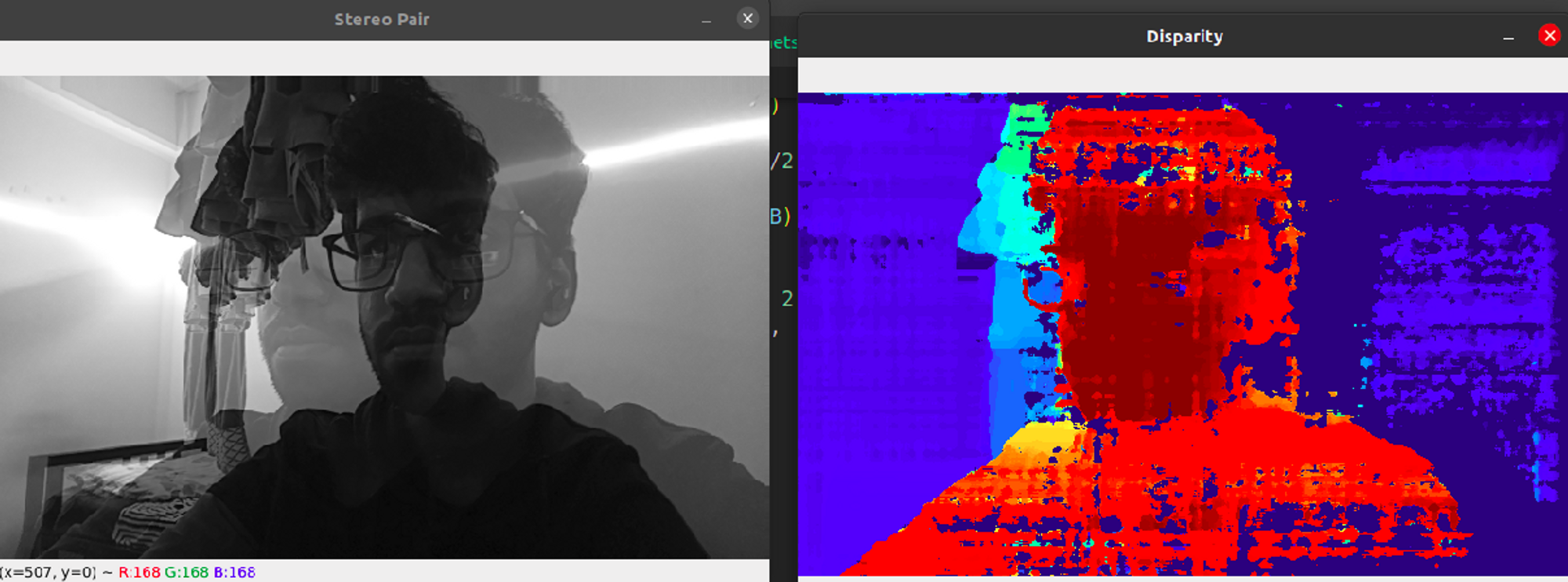
When the object is placed closer to the camera -
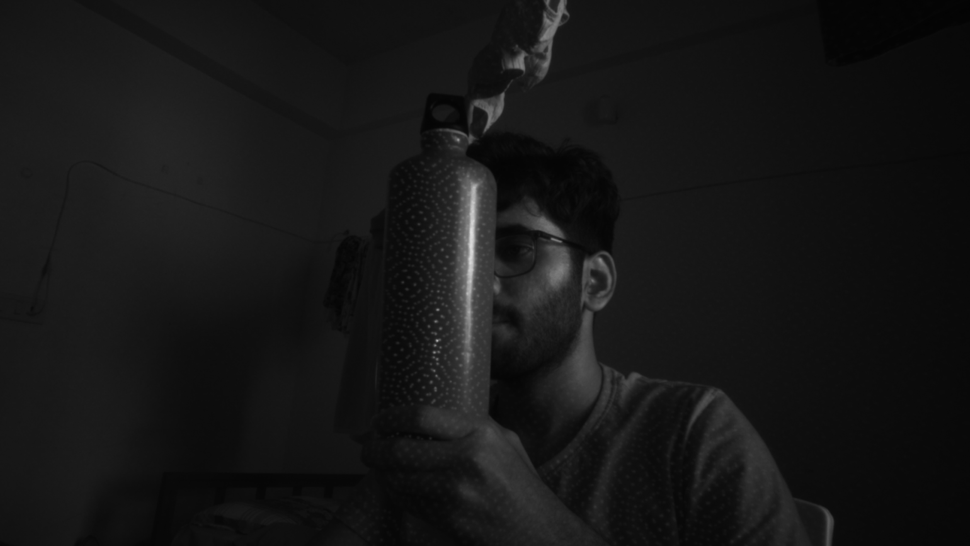
When the object is placed farther away from the camera -
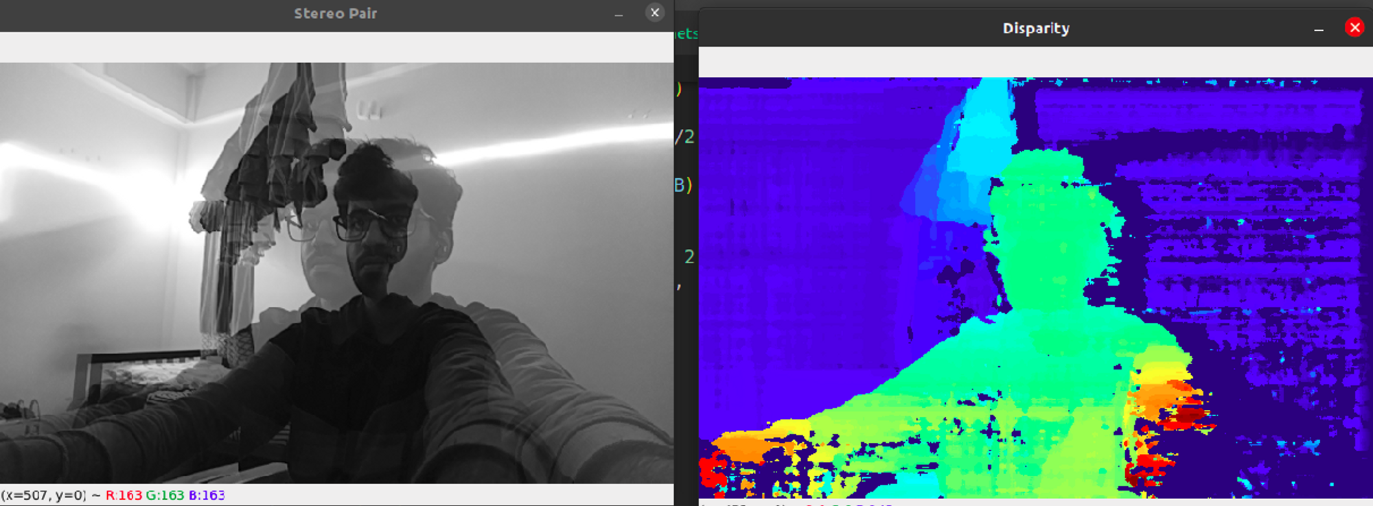
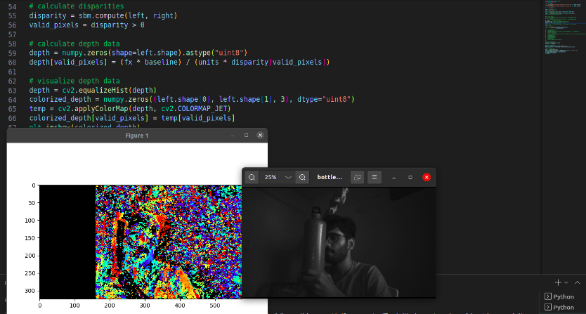
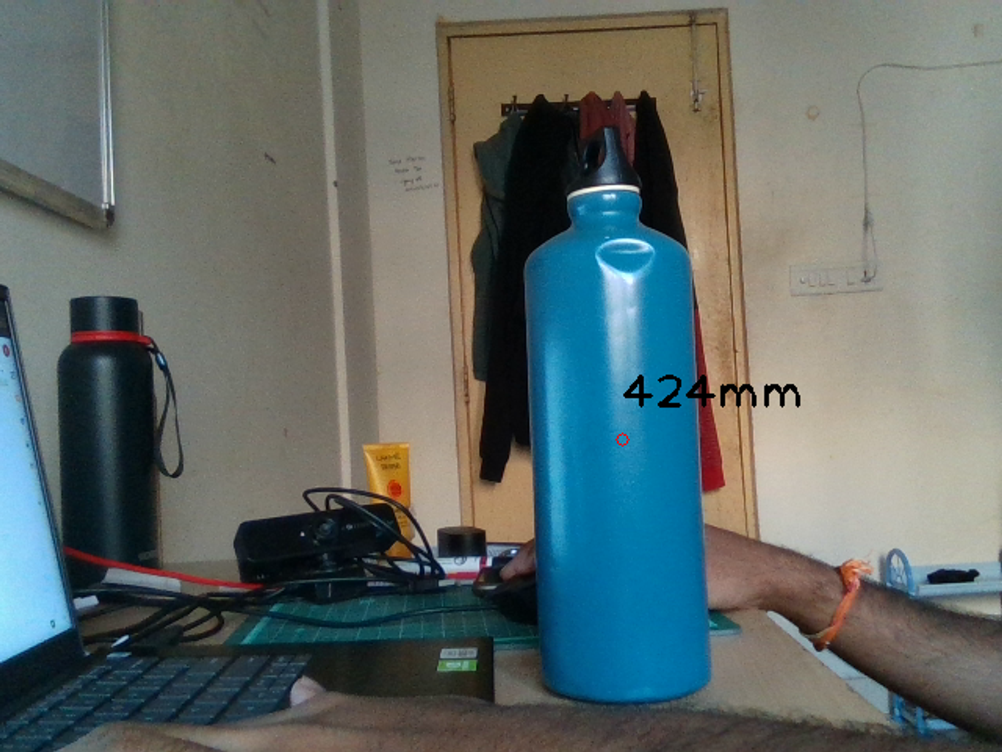
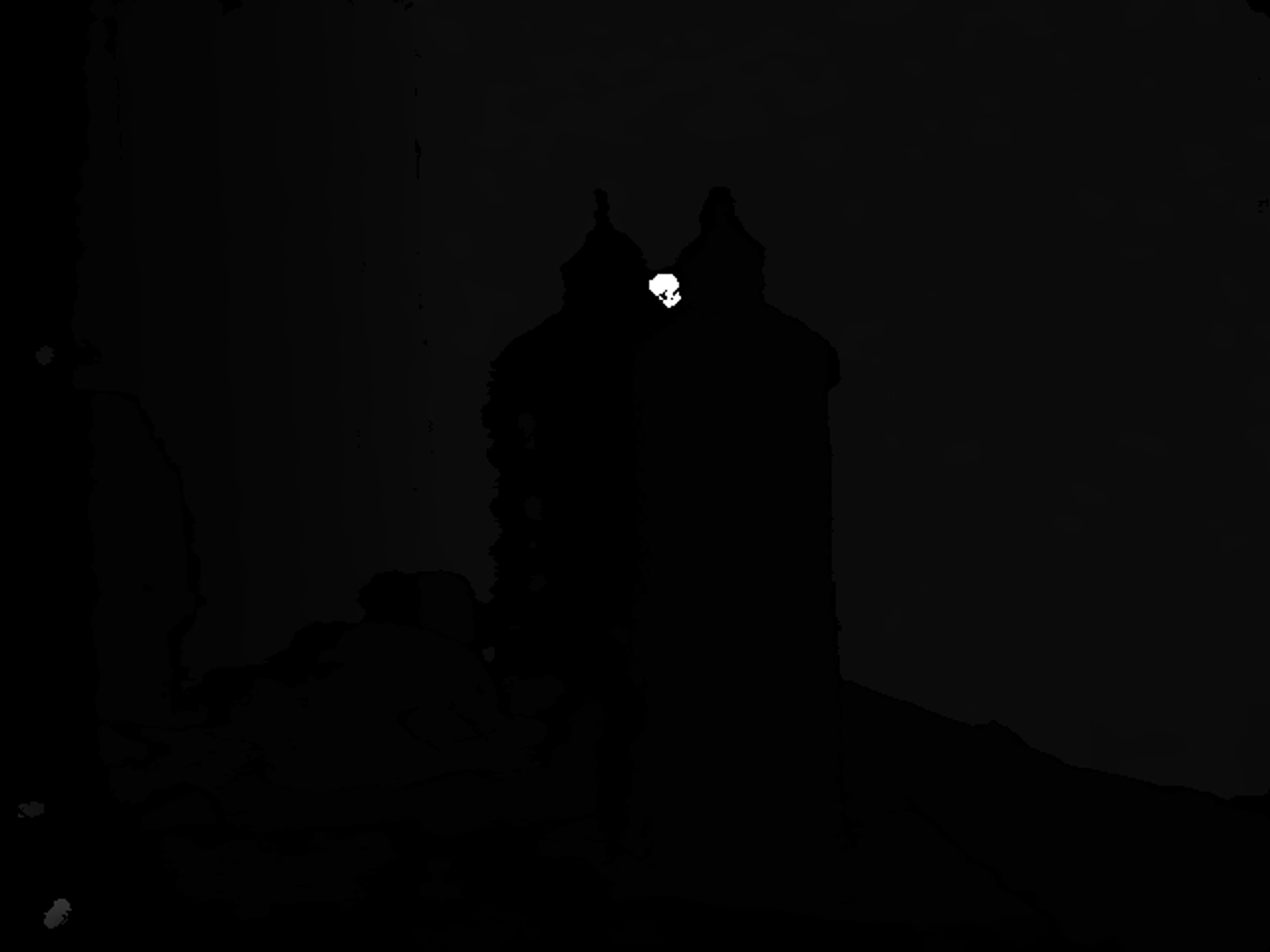
The same experiments are performed underwater, but now using the newly calibrated camera matrix. We obtain the depth values and the disparity map as follows -
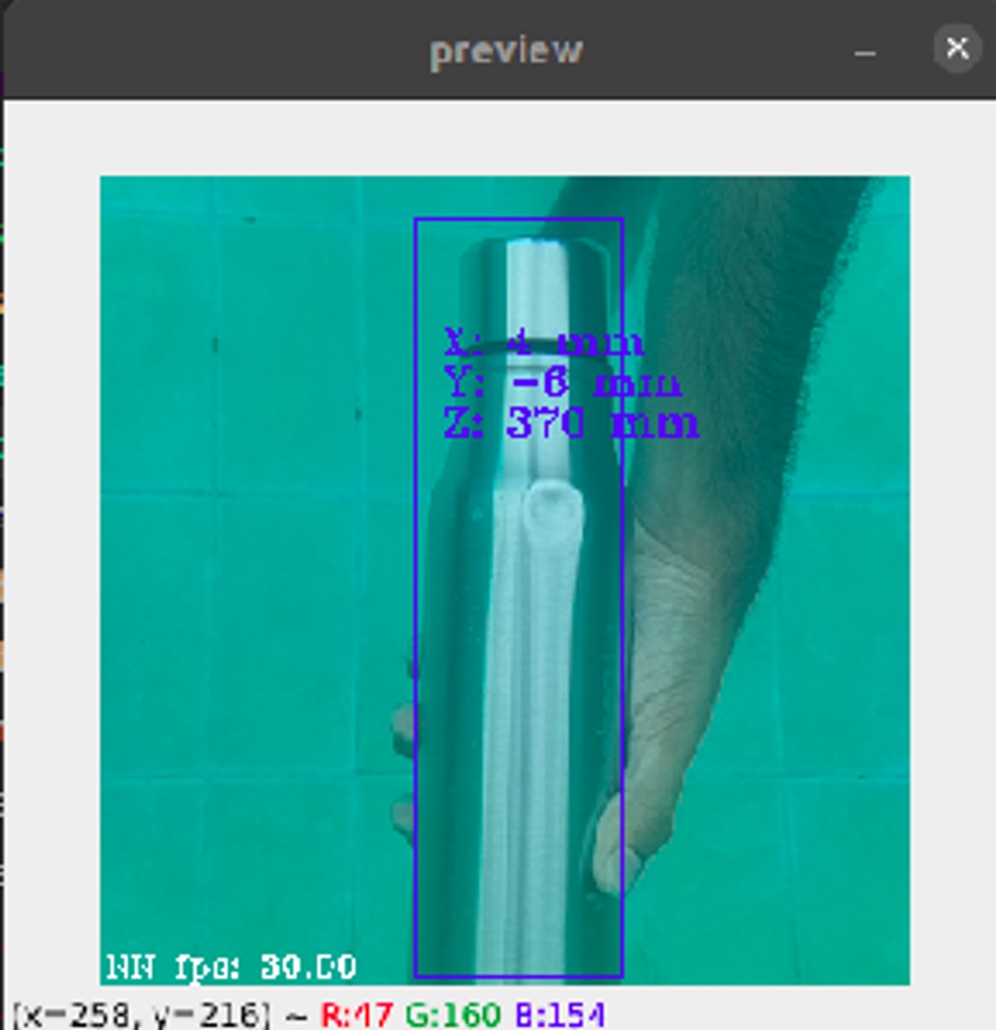
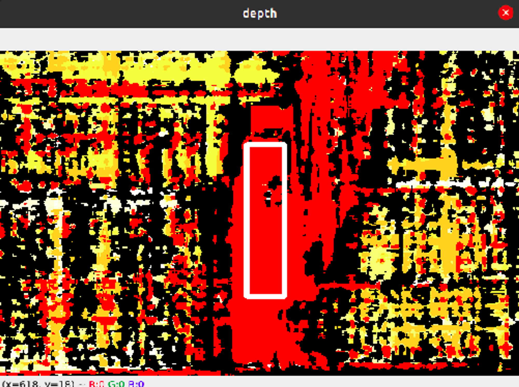
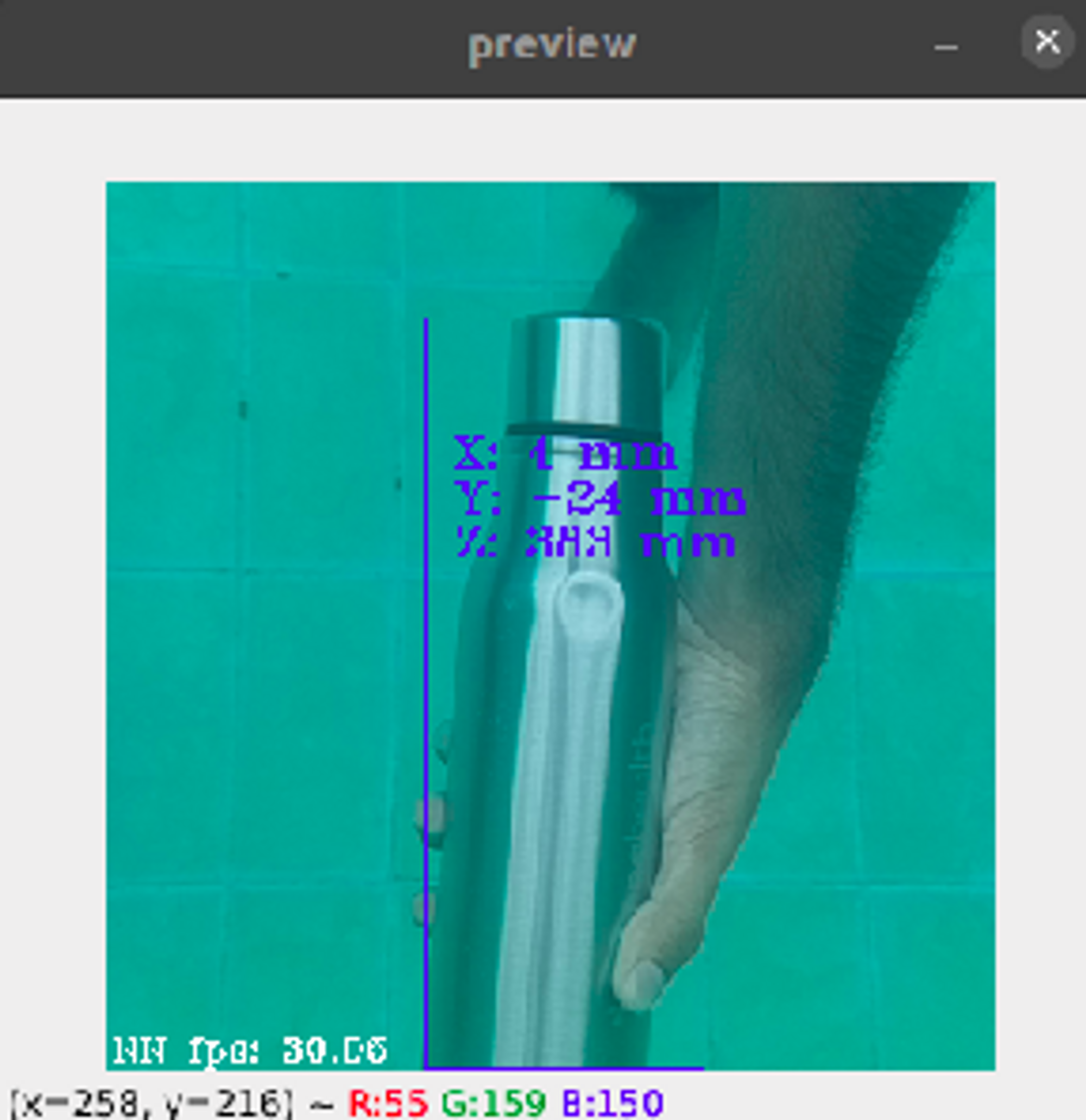
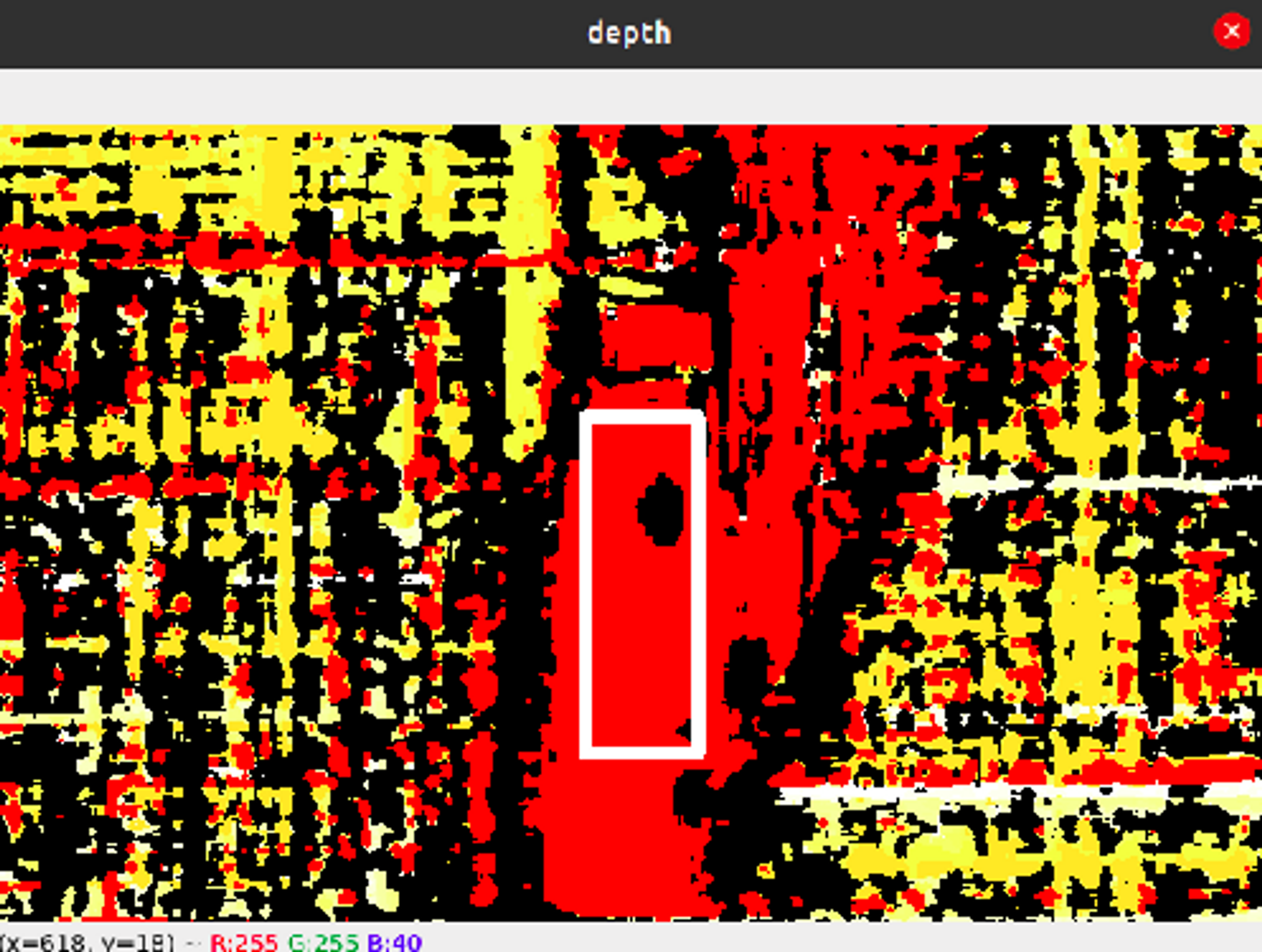
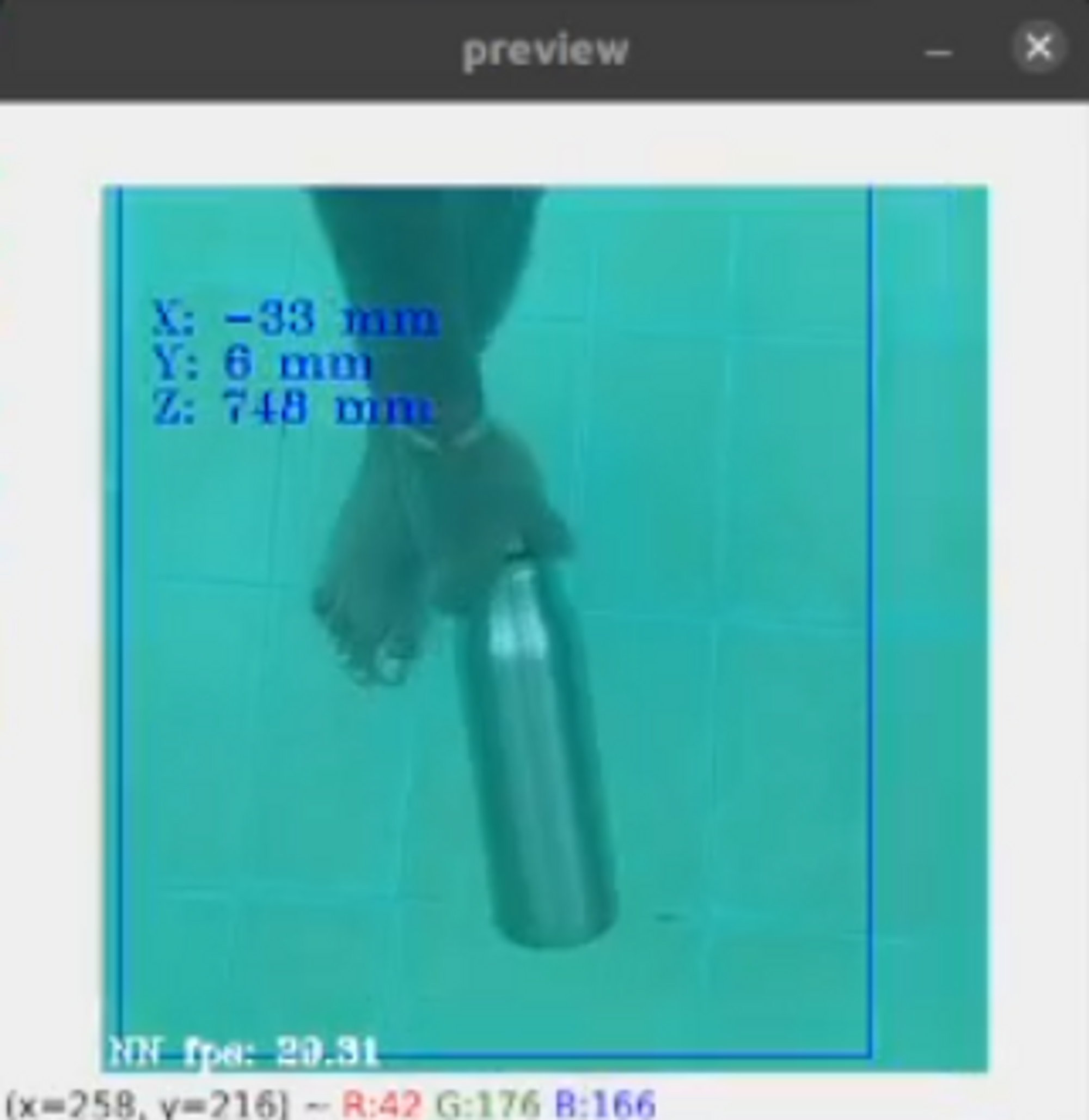
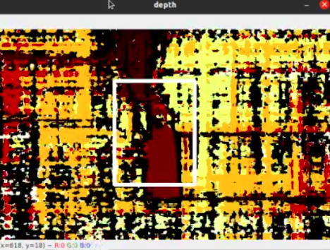
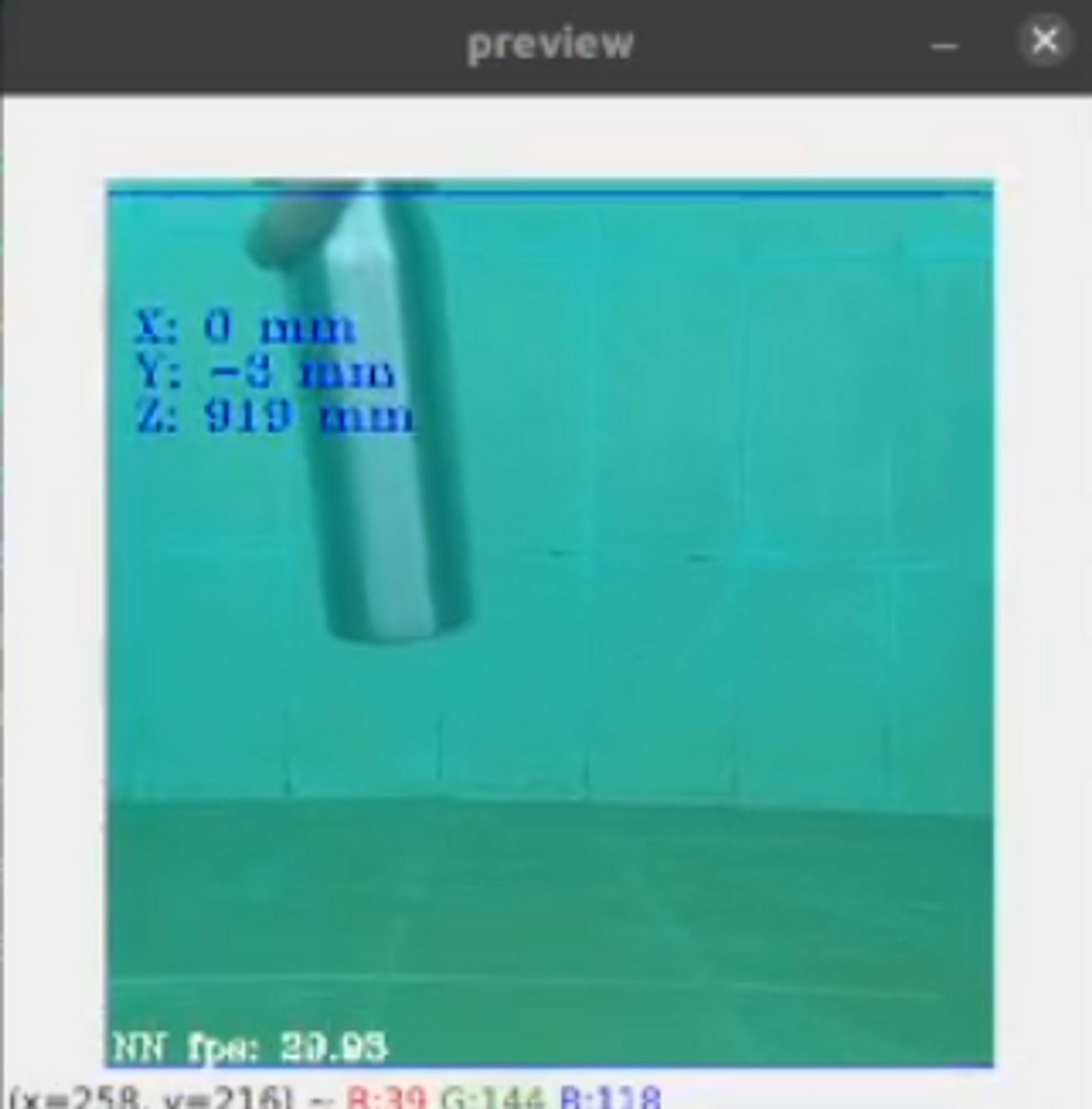
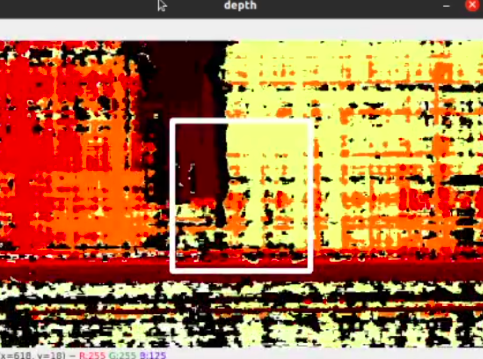
From the above images, we see that as the bottle is placed farther away from the depth camera setup, the value of the depth increases, and the disparity map changes accordingly. From the experiments performed above, we find that the depth camera can measure a depth of up to 1m (~3ft) underwater.
Camera Localization
As done earlier, the position of the depth camera can be estimated using the extrinsic parameters of the camera.
The following are the rotation and translation vectors obtained after calibration -
1
2
3
4
5
6
7
8
9
10
11
12
13
14
15
16
17
18
19
20
21
22
23
"rotationMatrix": [
                        [
                            0.9999324679374695,
                            -0.008666034787893295,
                            0.007746713235974312
                        ],
                        [
                            0.008631718344986439,
                            0.9999528527259827,
                            0.0044522895477712154
                        ],
                        [
                            -0.00778493145480752,
                            -0.0043851216323673725,
                            0.9999600648880005
                        ]
                    ],

"translation": {
                        "x": -7.581012725830078,
                        "y": -0.0006467599887400866,
                        "z": 0.040638044476509094
                    }
Conclusion
The work done so far includes camera calibration, block matching, disparity calculation, and depth estimation in an underwater environment. While performing the experiments, the depth camera could measure the depth of obstacles only up to a distance of 1m. This can be further improved by building a better canister for housing the depth camera and by improving the lighting conditions using subsea LED lights.
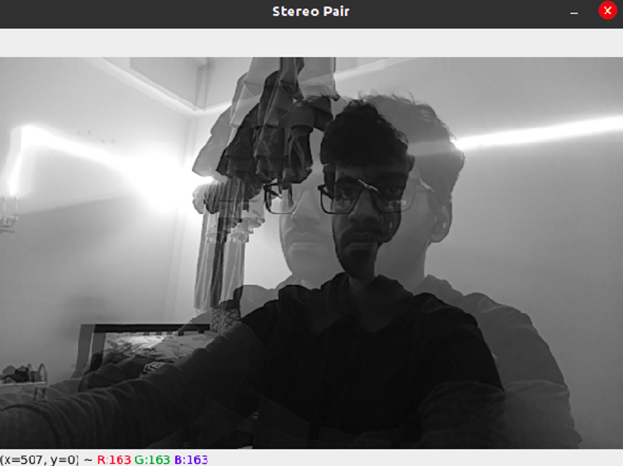
One major issue that I faced while working with the underwater camera setup was the problem of fogging. Due to the difference in temperatures at the back of the camera, which heats up, and the front of the camera, which is cold, fog begins to form on the left and right stereo cameras. This issue can also be solved by building a properly insulated canister.